Table iii—ratings and specifications—model 342 – Bryant 342S User Manual
Page 3
Attention! The text in this document has been recognized automatically. To view the original document, you can use the "Original mode".
S E P / 0 9 / 2 0 0 8 / T U E 0 3 : 3 3
UTC TECH PUB
F A X N o , 3 1 7 2 4 0 5 6 6 2
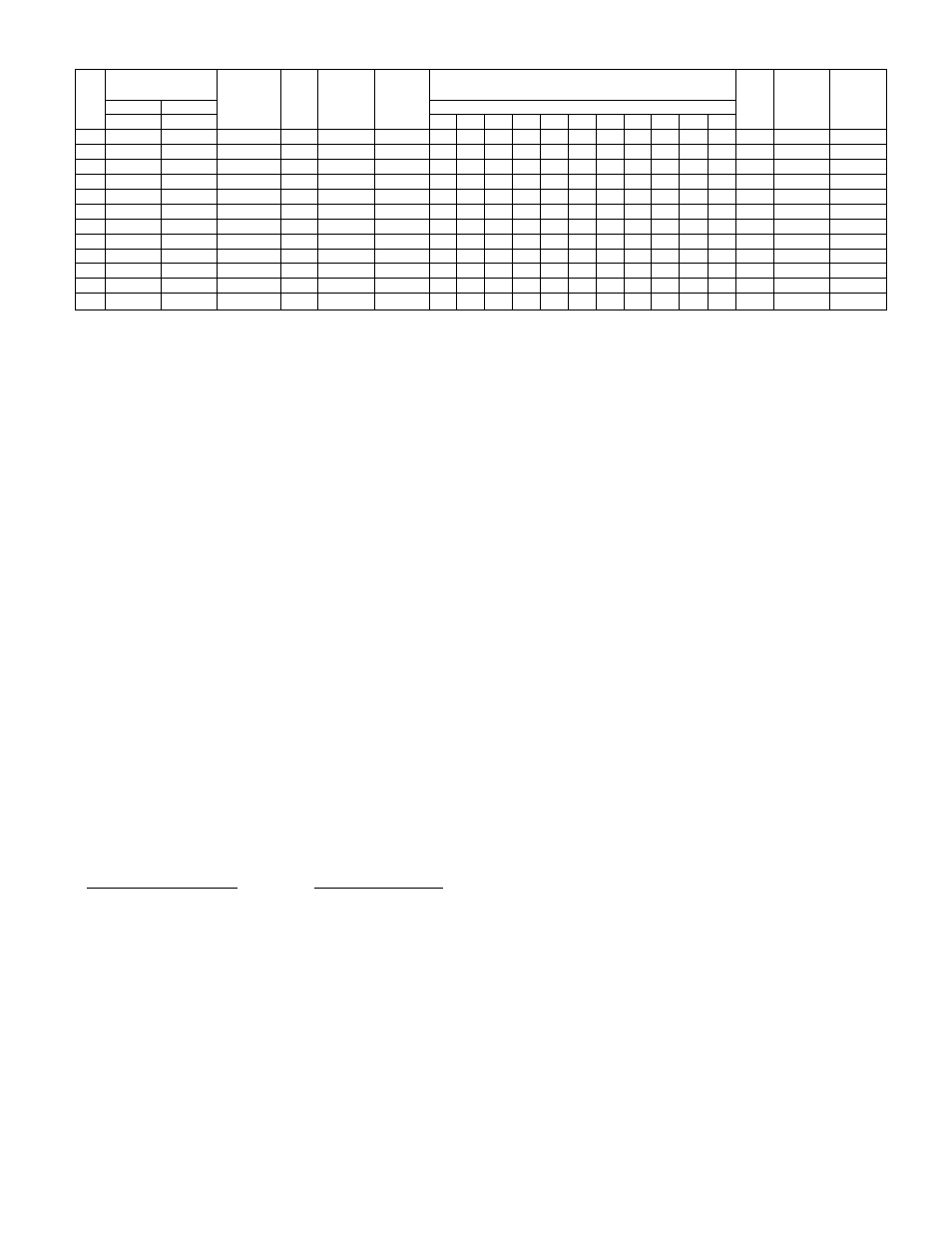
TABLE III—RATINGS AND SPECIFICATIONS—MODEL 342
Slzo
Equivalent
Sq Ft of
Steam
Radiation
Temp
Rise
’‘F
Total
Air
Delivery
CFM
Velocity
ft/mln
til
Effective Throw Mounting Haight
Fan
FIFM
Nominal
Motar
HP
Approx
Shipping
Weight
"’Ratings Btuh
Distance from Floor to Top of Hoator
Input
Output
8'
10'
12'
14'
16'
18'
20'
22'
24'
2B' 28'
30
30,OGO
24,000
100
Ф0
36Ы
5S5
16
13
1500
i/iM
65 "
50
50, O
dd
40,boo
1Й7
60
600
5Ô5
30
28
25
22
iSOO
1/40
84
76
75,000
60,000
250
70
900
615
36
33
30
28
1500
1/30
117
100
100,000
50,000
333
60
1200
675
45
43
40
38
35
33
30
1050
1/15
139
125
125,000
100,000
417
60
1500
720
55
53
50 ' " 48 ■45
43
40
38
1050
1/10
164
150
150,000
.120,000
500
60
1800
750
60
58
55
53
50
48
45
43
40
1050
1/10
^ 180
175
175,0(i0
140,000
5?3
60
21Ú0
850
65
63
60
58
55
53
50
48
45 ,
1050
1/5
212
200
200,000
160,000
667
60
2400
865
70
60
65
63
60
58
55
53
50
1050
1/5
235
225
225,000
180,000
750
60
2700
860
70
68
65
63
60
58
55
53
50
1050
1/5
258
250
250,000
200,000
833
60
3000
B50
05
63
60
58
55
53
50
43
45
1025
1/5
317
300
300,000
240,000
1000
60
3600
900
75
73
70
68
65
63
60
58
55
53
50
1050
(2) 1/10
378
400
400,000
320,000
1334
60
480Ô
1000
90
88
85
83
80
78
75
73
70
68
65
1025
(2) j/5
560
^The above ratings are approved for altitudes to.
2000
ft. For elevations above
2000
ft, reduce
ratings
4%
for each
1000
ft
above
sea level.
=i=’i=Effective throw aa shown is the horizontal distance in feet that the heated airstream travels from the outlet of the unit heater with
louvers
positioned
for maximum throw
with
air reaching the floor, Spread or
width
of the air pattern
is
approximately 20% of the'maximum
throw.
For
additional spread, use
vertical
louvers, Above data are test results,
Specific Location and Suspension Precautions
For general location and suspension information, refer to
Section II of Bryant form No, 33008Dl. b addition, the
following precautions should bs observed when selecting a
; mounting site,
1. Direct heated airstream toward area having greatest
heat loss.
2. For multiple installations, locate heaters so that each
will warm a specific area. Arrange so that the overall
air pattern results in a continuous circular flow of
warm air throughout the space,
3. Do not locate the heater in areas where combustion air
is limited,
4. If located in spaces equipped with exhaust fans,
provide sufficient makeup air.
5. Two l/2"inch pipe tappings are provided in the top
casing for use in suspending the heater. Use pipe
unions to join the unit heater to the ceiling hangar,
6. Do not lift the heater by the motor mount, manifold, or
louvers. Use a rope sling whenever this is possible.
IV. WIRING.
Make all electrical connections in accordance with the
National Electric Code and any_locaI codes .that may apply.
The unit must be grounded electrically in accordance with
the National Electric Code and local codes governing such
installations. A permanent and uninterrupted or unbroken
,.,ground,.is.es3enti al-to-minimi®ing.peEso naLin,j m,y_iLan-eiec=_
trical fault should occur.
If aluminum conductors are to be used, the wire size selec
ready for connections to a 116/60/1 power source. See
wiring diagram.
The heat anticipator on the thermostat should be set at 0.8
amps.
VI. STARTUP AND ADJUSTMENT
NOTE; Remove burner hold-down shipping bracket.
1. Start unit using procedure outlined on lighting instruc™
tion plate attached to heater.
2, Adjust pilot flame. Adjusting screw under screw cap on
pilot valve is used for this purpose,
For D4 controls, flame should be long enough for good
impingement on metal element of Bryant automatic
pilot. For D5 and D2 controls, flame should surround
thermocouple element of pilot and extend downward
to include 3/S to 1/2 inch of thermocouple. Flame
should never come in contact with any part of thermo
couple lead wire.
To adjust pilot flame on units equipped with Model A-
G43 valve, adjustment screw is located in pilot outlet
portion of valve body. Remove capscrew, make
.... . .nsoe.gsai'y. .adjustment, and replace capscrew,......................
"^3-r“6heck"input. "Input-s'hduld"be checked'-at metev'to-rH'S'ka"“
sure that it corresponds with input shown on rating
plate attached to unit. See Bryant form No, 39003D1
for method.
ted must have a Current capacity not less than that of the
copper wire specified and must not create a voltage drop be
tween the service panel and the unit in excess of 2% of the
unit rated voltage. As a minimum, aluminum wire must be
treated to prevent oxidation.
With electric power turned off, recheck all electrical con
nections (both factory and field) for tightness. Be sure to
check power supply connections, especially if aluminum
conductors are used.
The unit heater is completely wired at the factory and is
4. Final Checkout. Move thermostat setting above and
below room temperature several times, pausing be-
—^tween..,each^-“on—-and—off-’-c-yclfc...to-njake-8ut.e-.that-
main burners ignite properly.
Attach low-voltage test light to electrical leads of
gaa valve. With thermostat set above room tem
perature, close manual pilot valve. If light goes out
when pilot cools, pilot is functioning properly. Test
light should go out within 45 seconds after pilot gas
supply is turned off.
Check Operation of temperature limit control. Do this
by allowing burners to operate while fan is not running
to see that limit switch opens.
—
3
—