Bryant 342S User Manual
Page 4
Attention! The text in this document has been recognized automatically. To view the original document, you can use the "Original mode".
S E P / 0 9 / 2 0 0 8 / T D E 0 3 : 3 3 P M UTC TECH PUB
P A X N o , 3 1 7 2 4 0 5 6 6 2
Check all connections in gas piping for leaks. Use soap-
and-water solution.
VIL SERVICE AND MAINTENANCE
1.
Pilot Orifice - is located in bottom fitting of pilot and is
K
readily accessible for inspection and cleaning.
3. Main Burner Orifices - Orifice is readily unscrewed
from manifold after burner is removed,
3. Removing Main Burners - Lift rear of burner and push
it away from manifold enough to disengage orifice spud
from mixer shield. Then pull down and out of heater.
End of burner away from manifold seats in slotted
burner support. It is necessary to lift burner out of this
slot before attempting to push burner back. See Figure
12
.
NOTE: Disconnect the pilot tubing and wires to remove the
burner that holds the pilot. However, it is not necessary to
remove the pilot itself from the burner.
4. Cleaning - Heat exchanger tubes should be inspected
at regular intervals and cleaned when necessary.
a. Shut off gas and electricity. Heater should be cool.
b. Loosen two knurled-head screws to release rear
access door. Door will hang down freely.
c. Disconnect pilot tube and wireg.
d. Remove main burners and pilot.
e. Use stiff brush to scrub heat exchanger tubes.
Remove all loose scale and any soot that may have
collected.
f. Replace burners and pilot. Reconnect pilot tube
and wires.
g. Unit is now ready for relighting.
5. Oiling - Oil fan motor (s) yearly, or more often, with
enough drops of SAE No. 20 nondetergent oil to
overflow oil cup; or every 2 years, or more often, with
Anderol L-465* obtainable in tubes from your dealer.
(Bryant P/N 7O291D01). See FTB143.
*Lehigh Chemical Company
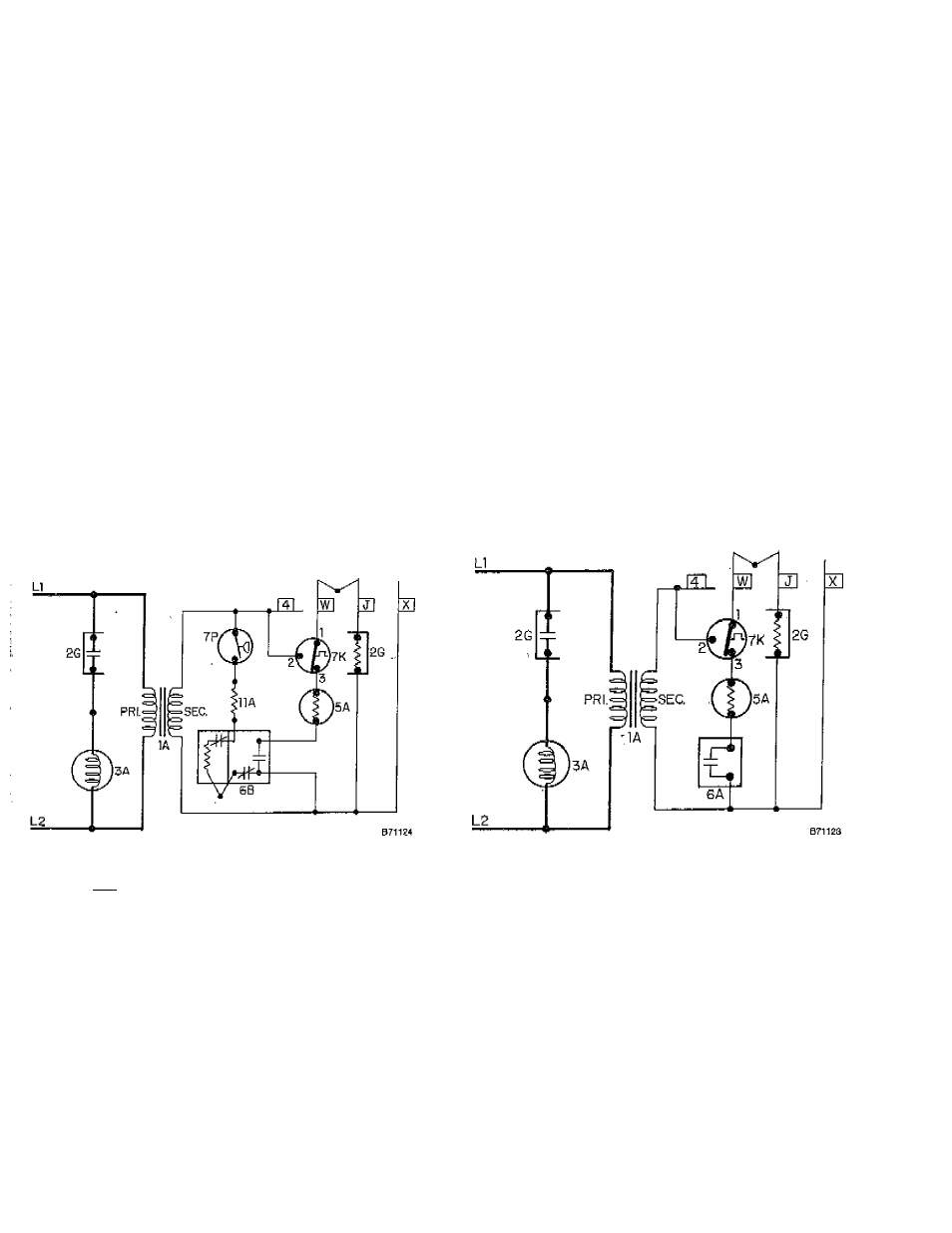
SIZES 30 THRU 150 UNIT HEATER WIRING DIAGRAMS
Figure 3^With 733 Pilot ihstaííed
:: :
4—УУ1Ш
FIIQÍ installed
LEGEND
1A
Transformer
6B
Pilot with Auto.
SG
Pan Relay—N.O,
Ignition Coil
ЗА
Fan Motor
7K
Temp Limit Control—
3A1
Fan Motor
SPOT—N.C.
3A2
Fan Motor
7P
Pressure Switch^—
3C
Fan Motor
SPST—N.O.
5A
Automatic Gas Valve
11A
Resistor
0A
Pilot Switch—No.O.
If wires are replaced, use 18 AWG
(None on Propane)
150“
C.,
3/64-inch thick insulation.
—
4
-