Bryant 342S User Manual
Bryant, 342s, Unit heaters
Attention! The text in this document has been recognized automatically. To view the original document, you can use the "Original mode".
S E P / 0 9 / 2 0 0 8 / T U E 0 3 : 3 2
UTC TECH PUB
F A X N o , 3 1 7 2 4 0 5 6 6 2
Bryant
AìrCondìtioning
Company
iiistructiòris
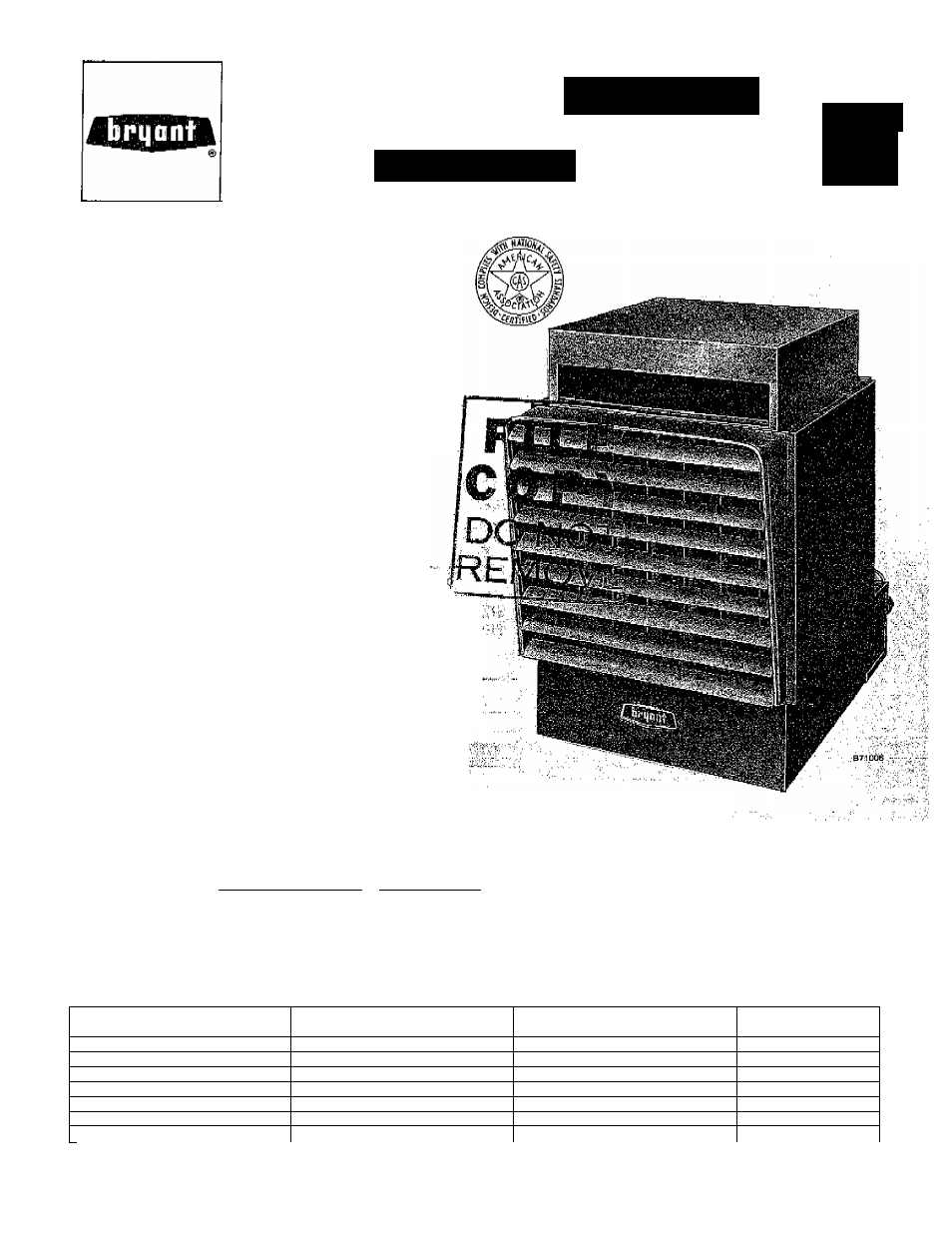
UNIT HEATERS
342S
: Series A
■Sizes 30
thru 400
Cancels; 39342D1
Before proceeding to install Models 342 and 342S Unit
Heaters, refer to Bryant form Ho, 39003D1 “Froeaduree for
Gas Appliances” (packaged with the equipment) for in
formation concerning combustion, venting, piping, and
other standard installation practices. The current edition of
the American National Standard “Installation of Gas Ap
pliances and Gas piping”, Z21.30, takes precedence over all
other reference publications pertinent to this -installation
instruction. Both models arc shipped factory-assembled,
Installation comprises the following;
* I. Inspection
* IL Location and Suspension
* III, piping '
lY,
.
*** V. Venting
VL Startup'arid Adjustment
VII, Service 0;and„
= the ■;apprOpriath;''settiQhs^ Pr^atit' farm No.' 3&003D1 (packaged '■ With'ixfhis^ ^ .;.■■■ ■, ■ ^ '■ ■■ - .' SPECIAL airplane a MANQAR AND : ; 1 . (5ARAGE APPLICATION PRECAUTIONS • NOTE.: cr aft ; Hangars, ” ahd^^HjFr'A ■; :NpT,;i':8g 2 ' Standard. .for . ' ' " " u O . . , .I.; 7 '■'.'li,'Ui'' 'A ■ '[,■ A ■', 1.,.......... 1, A clearance of 10 feeti.;tb.Th^;'battom;;.o 'ifHe;:to,p,;h'f.J/a^'/wing-nr'Vfus^ /hr,:,¡aircraft likely^-tp'fee;''.'o 7 ■ .''hoiisedah:,;,'-the' .h angar 'must ;be' ■ in aint'ained " >.■ ;'i■■ ,i X 'i ■2. A'^mmimumyclearanqe':''.oi/$;%et';::^^^^ .the bottom" ,'o.f ^thd '.'healtei:' ■ih./'hthef. .isepf ion^ .'pio^the ■.■;aircritft, hangar, such ' ¿ S ' ofhe'es' ''an'd '¿hops' Vliich ■'''bb'fh muni - cate .with areas used for servicing or storage, must be maintained. 39342D.PT3 11/1V4 Figure 1 4, A clearance of 6 inches from combustible maiterial must be maintained from the top and the sidep of thd A-The heater;imn-Si .also be gg'lQcated. th;at it is.protected.'._____........... heater. ■;.'/: from damage'by aircraft or other objects such as cranes 5, A service clearance of 18 inches at the rear and 12 ih- or movable scaffoldings. In addition, it must be located ches from any obstruction at the bottom of the heatdr "to be accessible for servicing and adjustment. must be maintained, " ' TABLE l-^GDNTROL OPTIONS^ i ' 7 ; COMPONENT ; •. 'PROPANE ;qA.s„,, .;■ ;........... ..:.7 "''7...'. .02.7,.'^ NATURAL 04 ' natural i D5 .Bryant Auto Pilot ...'.. e , . .■ ir-!:'' ,7" ".' ; ■' ,'X' " ' " ■' .'. "X ■ "'.„T ■Bryant'Gas 'Valve:!'■. ;■., ,'. ■ „" .7. .!7;'.7'7 ■ ,":'7. ■ ■ -7 ,7 ■ . X ■ . Gas Pressure .Begulator"! / " X'.^ ' X ■ . : . Transformer.: ' . „ . . X ; - . . . '■ ... . . . , . . „ 7; T 2. : : . ix;: ; ■,:........, , r , ; . ■X : 'X . ,d0D%'5hutpff..j,'.;'j.:>.,-: ......................,,/■, . . .,7'7:..'X'.7.: ... .. , ■ ,X ■' ..'7: ■v.-.'. Therrlno.co(jple FMot .............. v..... :'X......... 7.'v;,... Pilot.Belay„:or Pilo,t3tat„ . ■ .......... '¡..xx-',,.;. .'7. '■■ ■X". ^ ',■;.' /7 ""’All ithree bphonB,'.'.ay&ilable',.-on- 342 '8438 .■a're..-availablB .'with '1).3 .propane and 'D5 natural '.gaa only. ^ ■/■.■■'■'i, ■H=A'-643;Bryàn!f Gas ,’Valv.e wjthÙntsBral gae pressure rsgulatpr .is used ;on -IÌ4.'Hiid D5 ibf sizes 30 thru IBO; A-641 Gas Valve wimoUt regulator Used on-D2 for all 'sizes. -A-64l with separate gas ‘pressute Tegulator 'is'used on D4 and D5 for sises 175 'thru 40G. ■ ■ '
Gar ages; ” -