Bolens 140-830A User Manual
Page 13
Attention! The text in this document has been recognized automatically. To view the original document, you can use the "Original mode".
Linkage—Once a season lubricate all the pivot
points on the clutch, brake and lift linkage with
SAE 30 engine oil.
Wheel
Bearings—The
front
wheel
bearings
and
king pin bearings have Oilon PV 80 bearings that
require no lubrication.
Ball Joints—The ball joints and drag link ends are
permanently lubricated.
Fuel Shut-Off Valve and Filter
The valve and filter is located on the bottom of the
gasoline tank located at the extreme rear of the
tractor.
Turn the valve knob in to shut off the fuel flow.
Turn the valve knob out to operate the tractor. (See
figure 17.)
The entire valve can be pulled out to clean the
filter. When reassembling, place the rubber grom
met into the gasoline tank first, then push the
valve all the way in.
\
WARNING {
Only use factory approved parts if
repairs are needed on the gasoline
tank, grommet, valve or gasoline
line.
Grommet
Filter
I
h
Valve
FIGURE 17.
Installation of Tire to Rim
\
WARNING {
The following procedure must be
followed when removing or instal
ling a tire to the rim.
1. Lubricate the tire beads and rim flanges.
2. Do not exceed 30 p.s.i. when seating beads.
3. Adjust to recommended pressure after beads
are sealed.
Rear Wheel Tract Adjustment
The distance between the rear wheels can be
changed from wide to narrow by removing the rear
wheels one at a time and reversing them on the
hub.
With the rear wheels in the narrow position, the
outside of the rear wheels is even with the outside
of the front wheels.
With the rear wheels in the wide position, the in
side of the rear wheels is even with the inside of
the front wheels.
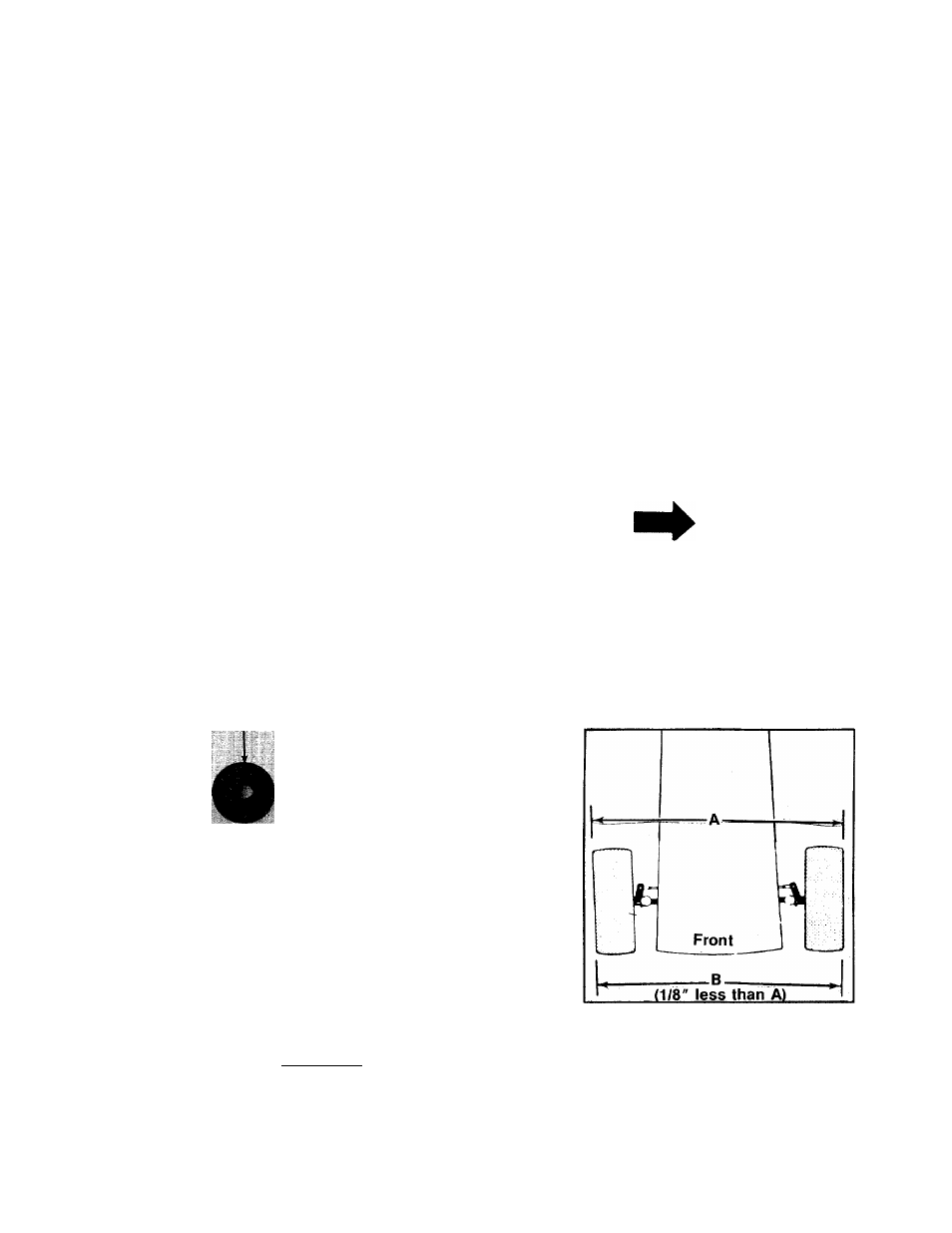
Wheel Alignment
The front wheels should toe-in approximately 1/8".
Measure the distances A and B on the front
wheels, (See figure 18.)
NOTE
Dimension B should be approx
imately
1/8
inch less than dimension
A.
To adjust the toe-in, loosen the hex jam nut,
remove the elastic locknut, lift the tie rod end out
of the hole in the steering arm and screw the tie
rod end in or out as necessary. (See figure 18.)
Reassemble the tie rod end after the correct align
ment is made.
FIGURE 18.
Drag Link
If the drag link or ball joints are changed, the new
assembly must be adjusted to the exact same
length as the original. If adjusted wrong it will
allow the tractor to turn sharper one direction than
the other.
13