Bolens 840 thru 849 User Manual
Page 16
Attention! The text in this document has been recognized automatically. To view the original document, you can use the "Original mode".
Speed
Control
Lever
Clutch-
Brake
Pedal
FIGURE 18.
Point on
Bracket
3/4" Shim
Variable Speed
Torque Bracket
Assembly
6. After engine stops completely, release the clutch-
brake pedal.
7. Remove the transmission cover by remo' ing the
parking brake knob, shift knob and twa truss
machine screws.
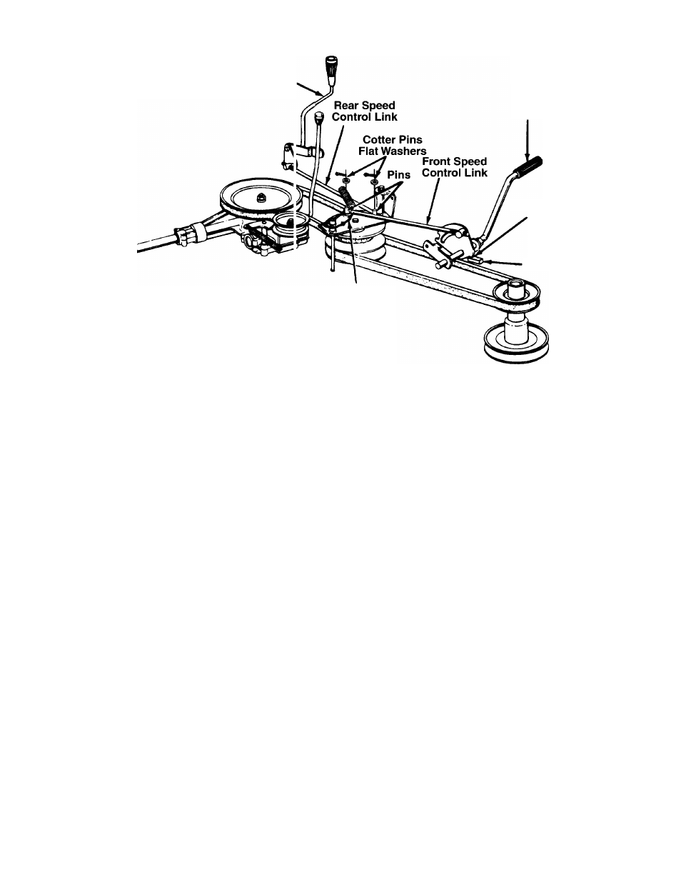
8 Disconnect the rear speed control link fiom the
var'able speed torque bracket by removing the
cotter pin and flat washer.
9. Models 820 thru 829: Place the speed control
lever in the first position.
Models 840 thru 849: Place the speed control
lever in the second position.
10. Disconnec; the front speed control link f om the
variable speed torque bracket by removing the
cotter pin and flat washer.
11. Place a 3/4" shim or other suitable objec t under
the point on the bracket on the clutch-bral< e pedal
as shown.
12. Thread the front speed control link in or oi t of the
ferrule until the hole in the link lines up with the pin
on the variable speed torque bracket. Sec jre with
the flat washer and cotter pin removed in step 10.
13. Push the rear speed control link backward using
light pressure, and hold it in this position as you
thread it into or out of the ferrule until the hole in
the link lines up with the pin on the variable speed
torque bracket.
Models 820 thru 829 Only: Turn the lirk three
more times (making it longer).
14. Move the speed control lever toward the rigf t so the
hole in the rear speed control link fits over th 3 pin on
the variable speed torque bracket. Secure with the
flat washer and cotter pin removed in step 8.
15. Remove the 3/4" shim from beneath the bracket
on the clutch-brake pedal.
LEVELING THE DECK
The sides of the deck should be the same distance
from the ground. The front of the deck should be 1/4"
to 3/8" lower than the rear of the deck. If adjustment is
required, refer to “Leveling the Deck” in Assembly
Instructions.
STEERING ADJUSTMENT
If the tractor turns tighter in one direction compared to the
other, the steering drag link must be adjusted. To adjust
the drag link follow these steps. Refer to figure 19.
1. Loosen hex jam nut (A) at the rear of the ball joint.
2. Loosen and remove hex nut (B).
3. Lift the threaded portion of the ball joint out of the
steering arm. Please do not misplace the hard
ware used to hold ball joint to steering arm. You
will need it again.
4. Set the front wheels facing straight ahead.
5. Turn the steering wheel to the right or the left to
match the alignment holes in the steering brace
and the steering gear.
6. Once aligned, drop a nail through the steering
brace and steering gear alignment holes.
7. Adjust the ball joint in or out on the drag link until
the threaded portion of the ball joint slips through
the hole in the steering arm. Make sure lock
washer (C) is in position between the ball joint and
the steering arm.
16