Bryant GAS-FIRED 454 User Manual
Page 7
Attention! The text in this document has been recognized automatically. To view the original document, you can use the "Original mode".
Charge the system with water as follows:
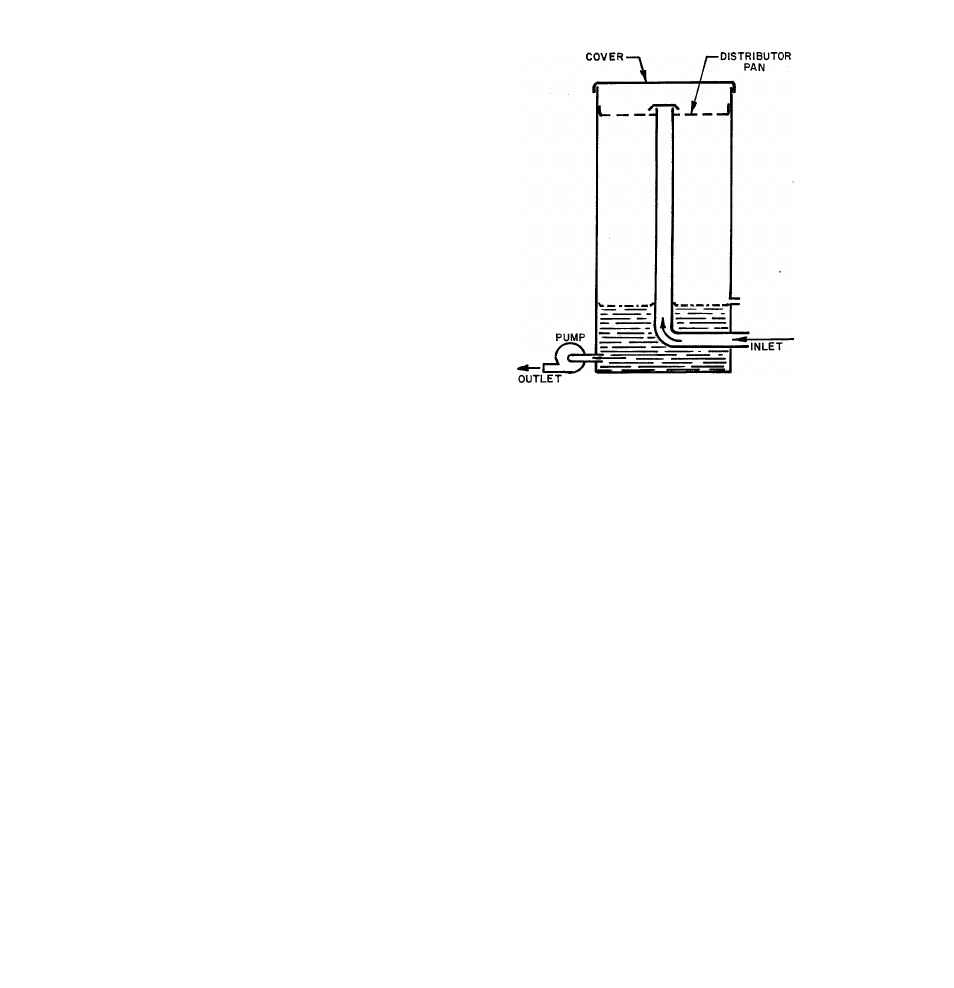
1. Remove the top casing and remove the
cover from the chilled water tank, see
F igure 4.
2. Add tap water until the distributor pan is
covered. A garden hose is useful for this
operation.
3 . Start unit (be sure gas is turned off). Con
tinue to add water until the system is primed
and the water is returning to the chiller tank.
4. Check water piping for leaks throughout
the chilled water system .
5. On the Model 36-454 remove the left side
access panel from unit and remove operating
level drain plug on the side of the chiller
tank.
6. The pump should still be running. When
water ceases to flow from the drain opening,
replace the drain plug.
7. With the water still circulating, add the
bag of chilled water additive by spreading
additive over the distributor pan. The addi
tive is sufficient for chilled water systems
containing up to 9 gallons of water. For sys
tems larger than 9 gallon capacity, add 1/2
package of additive for each 4 -1 /2 gallon
water capacity or fraction thereof. To esti
mate chilled water capacity of system, refer
to Table 4tr-
8. Replace chiller tank cover.
Figure 4 - Chiller Tank
TABLE IV
Water Capacity
Gallons
36-454 Chiller........................ ............................ -3^
X
-
3
Bryant 1-1/2 ton coil...................................... .
.6
Bryant 3 ton coil................................................. 1
1 ft 3/4-inch pipe................................................ .03
1 ft 1-inch pipe................................................... .05
VI. CHECKING THE UNIT OPERATION
j.. Be sure combination gas valve is off. Light
pilot as described on instruction plate.
2. Set thermostat to "cool"; set thermostat
fan switch to "auto"; set thermostat below
room temperature.
3 . Turn on main electric switch to unit.
4. Check indoor fan operation by turning
thermostat fan switch to "on" for continuous
operation. Move thermostat above room tem
perature and observe that the indoor fan re
mains on.
5. To place the system in operation, open the
main manual gas valve, replace all panels,
and set the thermostat at the desired temper
ature .
-
7
-
High Temperature Cut-Off
The high temperature circuit includes a high
temperature control located on the side of the
generator plus a high temperature lockout
(circuit breaker) located in the control box.
If the generator becomes overheated, the
contacts in the high temp control open,
causing the circuit breaker to go into lockout
position. The gas valve closes, the fan and
pumps stop and they will not recycle until
the circuit breaker is reset. To reset the
circuit breaker, push the red button extending
through the bottom of the control box. Be sure
to locate and correct the cause of the high
temp cut-out.
36/454