Bryant GAS-FIRED 454 User Manual
Page 6
Attention! The text in this document has been recognized automatically. To view the original document, you can use the "Original mode".
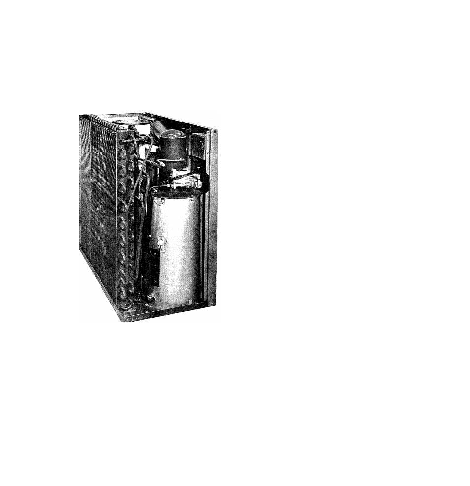
2. The gas supply pipe enters the unit through
a knockout located in the rear of the unit near
the left side. This unit requires one nipple
that is threaded into the 1 /2 -inch combination
regulator-shutoff valve, see Figure 3 .
3. A wrench-type shutoff valve should be in
stalled in the gas line within sight of, and
convenient to the unit.
Figure 3 • Gas Connections
4. Joint compound (pipe dope) which is re
sistant to the action of liquefied petroleum
gases should be applied sparingly and only to
the male threads of the joints .
5. Install a drip leg trap in the gas supply
riser leading to the unit. After gas pipe con
nections have been made, purge the lines, as
described below, and check for leakage. Use
a soap and water or other recommended
solution.
6. Never use matches, candles, flame or
other source of ignition to check for leaks.
Pilot
Light the pilot, using the procedure outlined
on the unit rating plate. However, when
lighting the pilot for the first time, perform (
the following additional steps;
1. If the supply line was not purged prior to
connecting the unit, it will be full of air.
Since it would take a long time to vent this
air through the small pilot port, it is recom -
mended that the pilot supply line be discon
nected at the pilot shutoff valve and the supply
line be allowed to purge until the odor of gas
is detected. Never purge gas lines into the
combustion chamber. Immediately upon de
tection of gas odor, reconnect the pilot supply
tube. Allow 5 minutes to elapse and light the
pilot in accordance with the instructions on
the lighting plate.
2. The pilot flame should be soft blue in
color.
a. For natural gas this flame should be of
sufficient length to provide good impinge
ment on the unimetal of the Bryant pilot.
The flame should extend upward and above
main burner ports .
3. If the pilot flame does not have the ap
pearance described above, it may be adjusted
at the manual pilot shutoff valve.
a . The valve is equipped with an adjustable
screw. Turn the handle to the full open
position, and remove the screw cap to ex
pose the adjustable screw. Turn adjusting
screw until flame has the desired appear
ance .
b. Replace screw cap.
V.
CHARGING THE SYSTEM WITH WATER
Coûtions:
1. Do not run the pump dry.
2. Do not operate the pump when the chiller
or chilled water lines are frozen. Freezing
temperatures, however, will not damage the
pump.
3 . The gas valve on the unit should be closed
when operating the unit during the following
procedures.
35/454
- 6 -