Installation of wheels, Attaching tongue to reservoir tank, Attaching the beam support – MTD 556 User Manual
Page 6: Latch bracket
Attention! The text in this document has been recognized automatically. To view the original document, you can use the "Original mode".
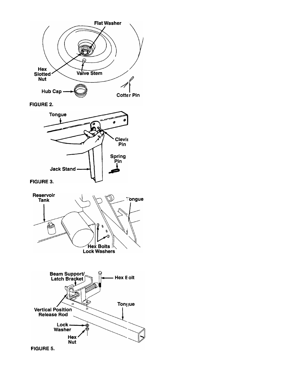
FIGURE 4.
Hex Nuts
INSTALLATION OF WHEELS
Attach the wheels to the reservoir tank assembly as
follows. See figure 2.
1. Block up the reservoir tank assembly about 8
inches.
2. Remove the cotter pin, hex slotted nut and flat
washer from each axle, and pull the plastic protec
tive cap from the hub of each wheel assembly.
3. With the grease seal facing inward and valve stem
outward, slide one wheel onto each axle. Use
care to avoid dislodging the outer tapered roller
bearing from wheel hub.
4. Place one flat washer just removed on each axle.
Secure with hex slotted nut. Tighten slotted nut
until snug, then back off approximately 1/3 turn or
until one of the slots on the slotted nut lines up
with the hole in the axle.
5. Insert cotter pins through slots in nuts and holes in
axle. Secure by bending the ends of the cotter
pins in opposite directions, using pliers and a
screwdriver.
6. Check the assembly of the wheels. There should
be no side to side play, and the wheels should
spin freely.
7. Place hub caps in position on wheels, and tap on
with a soft hammer or mallet. (It may be neces
sary to use a screwdriver to tap on the raised rib
of the hub cap.)
8. Check tires for correct air pressure.
ATTACHING TONGUE TO RESERVOIR TANK
1. The tongue is shipped with the jack stand already
attached to the tongue. The jack stand is in the
transport position. Remove the spring pin and cle
vis pin. Pivot the jack stand to the operating posi
tion (90°), and secure with the clevis pin and
spring pin. See figure 3.
2. Remove the two hex bolts, lock washers and hex
nuts on the front of the reservoir tank. Two 9/16"
wrenches are required. Place the tongue in posi
tion with jack stand facing down, and secure with
hardware just removed. Remove the assembly
from the blocks. See figure 4.
ATTACHING THE BEAM SUPPORT/
LATCH BRACKET
1. Remove the two hex bolts, lock washers and hex
nuts from the tongue, using two 9/16" wrenches.
2. Place the beam support/latch bracket on the
tongue as shown in figure 5. Secure with hex
bolts, lock washers and hex nuts just removed.
Tighten securely.