Hose clamps, Engine, Flexible pump coupler – MTD 556 User Manual
Page 13: Tires
Attention! The text in this document has been recognized automatically. To view the original document, you can use the "Original mode".
HOSE CLAMPS
Check the hose clamps on the suction hose (attached
to bottom of the pump) for proper tightness before
each use. Check the hose clamps on the return hose
at least once a season.
ENGINE
Refer to the separate engine manual for all engine
maintenance instructions.
Maintain engine oil as instructed in the separate
engine manual packed with your unit. Read and follow
instructions carefully.
Service air cleaner every 25 hours under normal con
ditions. Clean every few hours under extremely dusty
conditions. Poor engine performance and flooding
usually indicates that the air cleaner should be ser
viced. To service the air cleaner refer to the separate
engine manual packed with your unit.
The spark plug should be cleaned and the gap reset
once a season. Spark plug replacement is recom
mended at the start of each season; check engine
manual for correct plug type and gap specification.
Clean the engine regularly with a cloth or brush. Keep
the cooling system (blower housing area) clean to per
mit proper air circulation which is essential to engine
performance and life. Be certain to remove all dirt and
combustible debris from muffler area.
FLEXIBLE PUMP COUPLER
The flexible pump coupler is a nylon “spider” insert,
located between the pump and engine shaft. Over a
period of time, the coupler will harden and deteriorate.
Replacement is needed if you detect vibration or noise
coming from the area between the engine and the
pump. If the coupler fails completely, you will experi
ence a loss of power.
IMPORTANT; Never hit the pump shaft in any man
ner, as any blow will cause permanent damage to
the pump.
i/Vhen replacing the flexible pump coupling, proceed
ÎS follows. Follow the instructions carefully as the
îlignment is very critical.
1. Disconnect the spark plug wire from the spark
plug, and secure it away from the spark plug.
2. Using a 1/2 inch wrench, remove three nuts and
lock washers which secure the pump to the cou
pling shield. Two nuts are at the bottom corners
and one is in the top center.
3. Remove the pump.
4. Rotate the engine by pulling starter handle until
engine coupling half set screw is at bottom.
Loosen set screw using 7/64 inch Allen wrench.
Slide coupling half off of engine shaft.
5. Loosen set screw on pump coupling half, and
remove coupling half.
6. Slide new engine coupling half onto the engine
shaft until the end of the shaft is flush with the
inner portion of the coupling half. (There must be
space between end of the engine support bracket
and coupling half.) Tighten set screw.
7. Install pump coupling half and key on pump shaft.
Rotate coupling half until set screw faces down.
Do not tighten set screw.
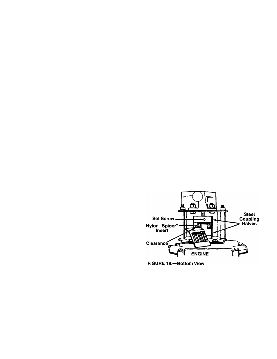
8. Install nylon “spider” onto engine coupling half.
9. Align pump coupling half with nylon “spider” by
rotating engine using starter handle. Slide cou
pling half into place while guiding three mounting
bolts through holes in pump support bracket.
10. Secure with nuts and washers removed earlier.
11. Set .010 to .060 inch clearance between the nylon
“spider” and the engine coupling half by sliding a
matchbook cover between the nylon “spider” and
the engine coupling half and moving pump cou
pling half as needed. Secure pump coupling half
with set screw. See figure 18.
NOTE: Make certain proper clearance is obtained
before tightening set screw.
12. Reattach spark plug wire to spark plug.
PUMP
TIRES
Recommended operating tire pressure is 12 to 15
p.s.i. (sidewall of tire may give tire manufacturer’s rec
ommended pressure). Maximum tire pressure under
any circumstances is 30 p.s.i. Equal tire pressure
should be maintained on all tires.
When installing a tire to the rim, be certain rim is clean
and free of rust. Lubricate both the tire and rim gener
ously. Never inflate to over 30 p.s.i. to seat beads.
13