Beam and splitting wedge, Hose clamps, Engine – MTD 249-610-000 User Manual
Page 9: Flexible pump coupler, I warning i, Note
Attention! The text in this document has been recognized automatically. To view the original document, you can use the "Original mode".
BEAM AND SPLITTING WEDGE
Lubricate the beam where it contacts the ram with
grease before each use to obtain years of service.
HOSE CLAMPS
Check the hose clamps on the suction hose (attached
to bottom of the pump) for proper tightness before each
use. Check the hose clamps on the return hose (be
tween beam and cylinder) at least once a season.
ENGINE
Refer to the separate engine manual for all engine
maintenance instructions.
Maintain engine oil as instructed in the separate
engine manual packed with your unit. Read and follow
instructions carefully.
Service air cleaner every 25 hours under normal con
ditions. Clean every few hours under extremely dusty
conditions. Poor engine performance and flooding
usually indicates that the air cleaner should be ser
viced. To service the air cleaner refer to the separate
engine manual packed with your unit.
The spark plug should be cleaned and the gap reset
once a season. Spark plug replacement is recommend
ed at the start of each season; check engine manual
for correct plug type and gap specification.
Clean the engine
regularly with a cloth or brush. Keep
the cooling system (blower housing area) clean to per
mit proper air circulation which is essential to engine
performance and life. Be certain to remove all dirt and
combustible debris from muffler area.
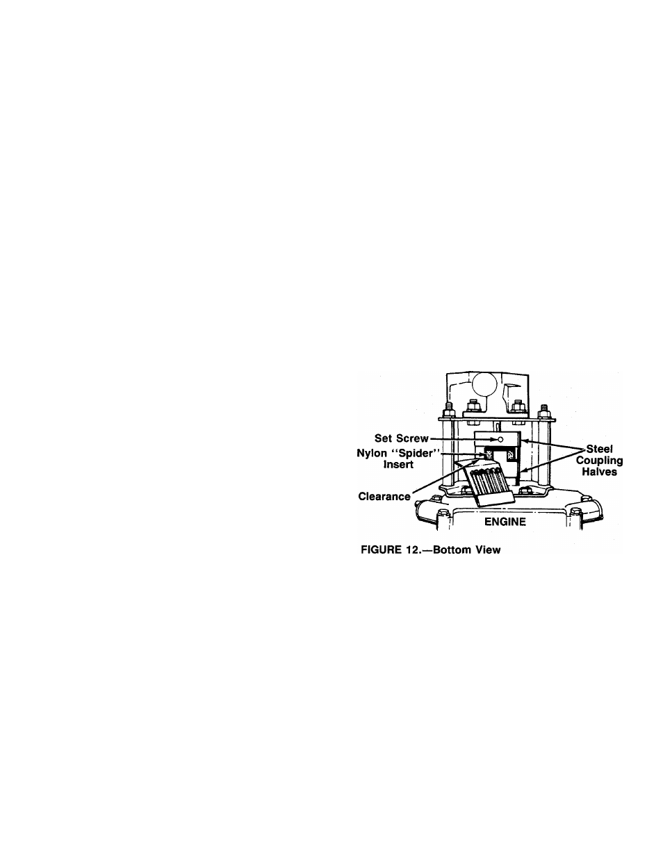
FLEXIBLE PUMP COUPLER
The flexible pump coupler is a nylon “spider” insert,
located between the pump and engine shaft. The align
ment is very critical. Over a period of time, the coupler
will harden and deteriorate. For a replacement flexible
pump coupler, order part number 717-0891.
A
i WARNING i
Never hit the pump shaft in any manner,
as any blow will cause permanent
damage to the pump.
When replacing the flexible pump coupling, proceed
as follows.
1. Place the coupling half onto the engine shaft. Make
certain there is clearance between the coupling
half and the engine. Tighten the set screw.
2. Mount the pump onto the coupling support bracket.
Tighten securely.
3. Carefully slide coupling half onto pump shaft (make
certain set screw is loose). Slide the key into place
on the shaft.
4. Install the nylon “spider” insert into coupling half
on the engine shaft.
5. Place the coupling shield in position on the hex
bolts. Rotate the keyway on the pump shaft so it
is toward the bottom.
6. Attach the coupling support bracket to the hex
bolts, carefully sliding the coupling half over the
“spider” insert. Secure coupling shield and coup
ling support bracket with lock washers and hex
nuts. Tighten securely.
7. Adjust the two coupling halves (steel) so there is
between .010" and .060" clearance between the
two halves (at least the thickness of a matchbook
cover, up to 1/16" maximum). See figure 12.
Tighten the set screw in the coupling half on the
pump shaft.
►NOTE
Make certain proper clearance is ob
tained before tightening set screw.
PUMP
CARBURETOR ADJUSTMENT
A
t WARNING
i
If any adjustments are made to the
engine while the engine is running
(e.g. carburetor), keep clear of all moving
parts. Be careful of heated surfaces and
muffler.
Minor carburetor adjustment may be required to com
pensate for differences in fuel, temperature, altitude or
load. Improper adjustment will cause stalling when split
ting is under load, hard starting and higher fuel con
sumption.
Refer to the separate engine manual packed with your
log splitter for carburetor adjustment information.