Pressure hose, Final assembly, Operation – MTD 249-620-003 User Manual
Page 8: Initial preparation, Note
Attention! The text in this document has been recognized automatically. To view the original document, you can use the "Original mode".
Pressure
Hose
Control
Valve
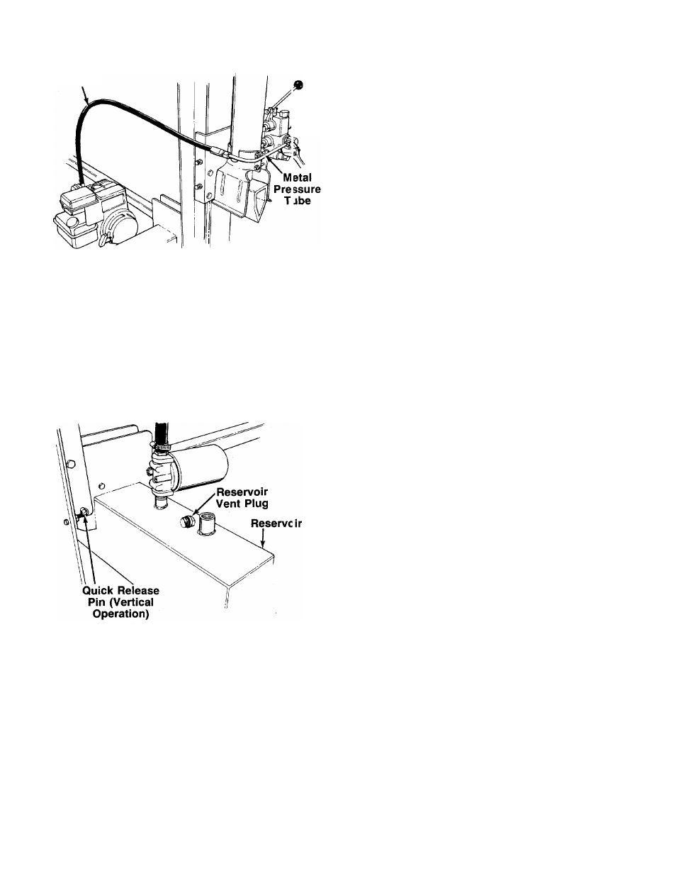
Pressure Hose
The pressure hose is attached to the top of the pump.
-Route the hose as shown in figure 10. Place the metal
pressure tube in position on the fitting on top of con-
troi valve. Secure with the compression nut on the
pressure tube, using an adjustable wrench.
FINAL ASSEMBLY
1. Make certain all nuts, bolts and hose clamps are
tightened securely.
2. Before operating the log splitter, make certain to
follow the “Initial Preparation” instructions in the
Operation Section.
FIGURE 10.
OPERATION
INITIAL PREPARATION
1. Place log splitter on a firm, level surface. Fo' ver
tical operation, remove the quick release pin from
the latch bracket. Place the beam in the vertical
position. Place the quick release pin througi the
holes in the beam mounting plates anc the
brackets on the reservoir tank. See figure ' 1.
FIGURE 11.
2. Service engine with gasoline and oil as instructed
in the separate engine manual packed with your
log splitter.
3. Lubricate the beam area where splitting wedg e will
slide with engine oil (DO NOT USE GREASE).
Make certain to oil both front and back of the beam
face.
4. Fill the reservoir tank as follows.
a. Remove reservoir vent plug. See figur
Using Dexron II automatic transmission fluid,
fill reservoir to the top. Replace vent plug
securely.
b. Disconnect the spark plug wire.
Prime the
pump by pulling the recoil starter, to turn the
engine over, approximately 10 times.
Recon
nect the spark plug wire.
c. Start engine. Use the control handle to extend
the wedge to the far extended position. Leave
the wedge in this position (do not retract).
d. Refill tank to within 1V
2" to 2" from the top of
the tank. Total capacity of system is approx
imately 7.6 gallons.
e. Now retract the wedge. Extend and retract the
wedge fully 10 to 12 complete cycles to remove
trapped air in the system (system is “self
bleeding”).
f.
Refill the reservoir
to within 1 Vz" to 2" from
the top of the tank. Much of the original fluid
has been drawn into the cylinder and hoses.
Make certain to refill the reservoir, to prevent
extreme damage to the hydraulic pump. Failure
to refill the tank will
void your warranty.
NOTE
Some fluid may overflow from the
vent plug as the system builds heat
and the fluid expands and seeks its
own level.
A
WARNING
Do not operate the log splitter without
the
proper
amount
of
transmission
fuild in the reservoir tank.