Flexible pump coupler, Note, Tire pressure – MTD 249-620-003 User Manual
Page 12: Installation of tire to rim, I warning, Off-season storage
Attention! The text in this document has been recognized automatically. To view the original document, you can use the "Original mode".
Clean the engine
regularly with a cloth or brusli. Keep
the cooling system (blower housing area) clear to per
mit proper air circulation which is essential to engine
performance and life. Be certain to remove all dirt and
combustible debris from muffler area.
PUMP
FLEXIBLE PUMP COUPLER
The flexible pump coupler is a nylon “spider’ insert,
located between the pump and engine shaft. The align
ment is very critical. Over a period of time, the coupler
will harden and deteriorate. For a replacement flexible
pump coupler, order part number 717-0891.
A
WARNING
Never hit the pump shaft in any manner,
as any blow will cause permanent
damage to the pump.
When replacing the flexible pump coupling, p roceed
as follows.
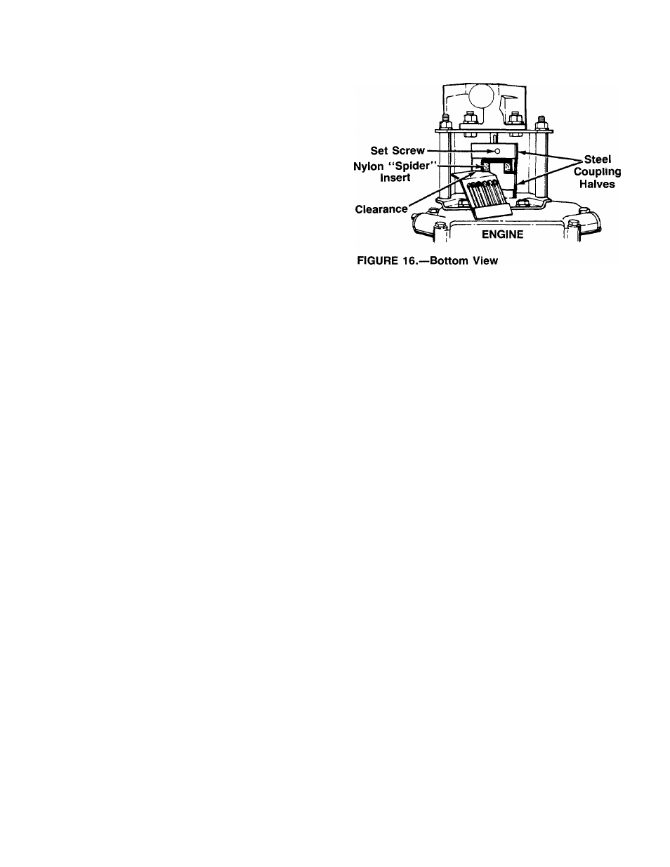
1. Place the coupling half onto the engine shal t. Make
certain there is clearance between the CDupling
half and the engine. Tighten the set screw.
2. Mount the pump onto the coupling support bracket.
Tighten securely.
3. Carefully slide coupling half onto pump shalt (make
certain set screw is loose). Slide the key inio place
on the shaft.
4. Install the nylon “spider” insert into coupling half
on the engine shaft.
5. Place the coupling shield in position on he hex
bolts. Rotate the keyway on the pump sh aft so it
is toward the bottom.
6. Attach the coupling support bracket to ihe hex
bolts, carefully sliding the coupling half e ver the
“spider” insert. Secure coupling shield and coup
ling support bracket with lock washers e nd hex
nuts. Tighten securely.
7. Adjust the two coupling halves (steel) so there is
between .010" and .060" clearance between the
two halves (at least the thickness of a ma chbook
cover, up to 1/16" maximum). See figure 16.
Tighten the set screw in the coupling hab on the
pump shaft.
ob-
NOTE
Make certain proper clearance is
tained before tightening set screw.
TIRE PRESSURE
Check sidewall of tire for manufacturer’s recommended
maximum tire pressure. If this information does not ap
pear on your tire, maximum tire pressure under any cir
cumstances is 30 p.s.i. Equal pressure should be
maintained on both tires.
INSTALLATION OF TIRE TO RIM
A
I WARNING {
The following procedure must be fol
lowed when removing or installing a
tire to the rim.
1. Be certain rim is clean and free of rust.
2. Lubricate both the tire and rim generously.
3. Never inflate to over 30 p.s.i. to seat beads. Ex
cessive pressure when seating beads may cause
tire/rim assembly to burst with force sufficient to
cause serious injury.
OFF-SEASON STORAGE
To avoid engine problems, the fuel system should be
emptied before storage of 30 days or longer. Follow
these instructions.
1. Drain the fuel tank. Start the engine, and let it run
until the fuel lines and carburetor are empty.
A
WARNING
DO
NOT
DRAIN
FUEL
WHILE
SMOKING, OR IF NEAR AN OPEN FIRE.
2. Drain all the oil from the crankcase (this should be
done after the engine has been operated and is
still warm) and refill the crankcase with fresh oil.
12