Attaching the engine and pump assembly, Attaching the control handle, Attaching the hoses suction hose – MTD 249-620-003 User Manual
Page 7: Return hose
Attention! The text in this document has been recognized automatically. To view the original document, you can use the "Original mode".
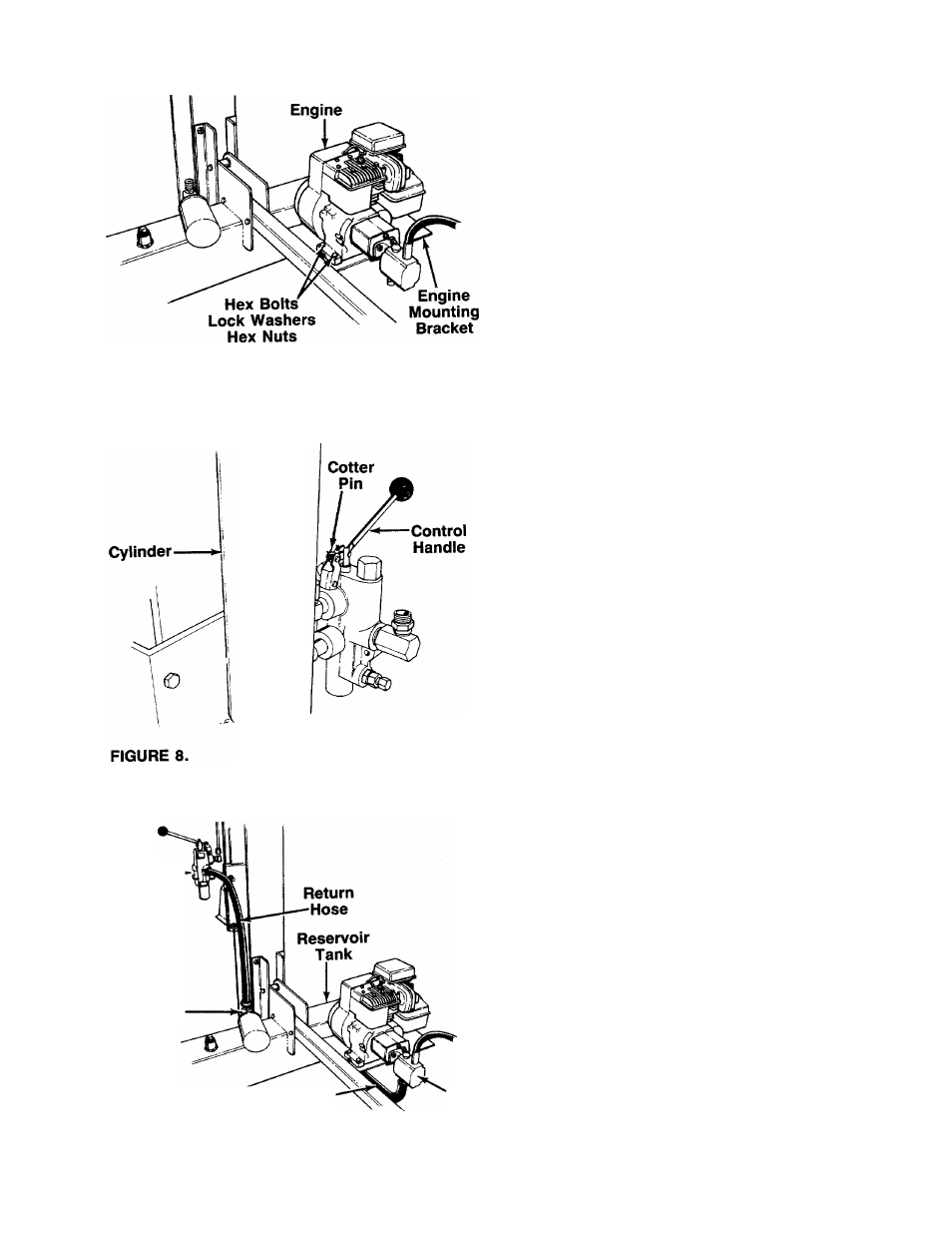
ATTACHING THE ENGINE AND PUMP ASSEMBLY
1. Using two 1/2" wrenches, remove the four hex
bolts, lock washers and hex nuts which secure the
base of the engine to the bottom of the shipping
carton.
2. Place the engine and pump assembly in position
on the engine mounting bracket as shown in figure
------- 7. Secure with hardware just removed. Tighten
securely.
FIGURE 7.
ATTACHING THE CONTROL HANDLE
1. The control handle and the return hose are attach
ed to the metal pressure tube with a cable tie for
shipping purposes only. Cut and remove the cable
tie.
2. The bottom of the control handle is already at
tached to the valve with a cotter pin and clevis pin.
Remove the second cotter pin and clevis pin which
is attached to the valve only. Place the handle in
position, and secure using the second cotter pin
-------and clevis pin. See figure 8.
Control
Valve
Filter
Head
Suction-
Hose
Pump
FIGURE 9.
ATTACHING THE HOSES
Suction Hose
1. The suction hose is attached to the reservoir tank,
beneath the engine mounting plate. Loosen the
hose clamp on the free end of the hose using a
screwdriver.
2. Attach the end of the hose to the fitting on the bot-
-------tom of the pump. See figure 9. Place the hose
clamp at the base of the fitting, and tighten
securely.
Return Hose
1. The return hose is attached to the bottom of the
valve. Loosen the hose clamp on the free end of
the hose using a screwdriver.
2. Attach the end of the hose to the fitting on top of
the filter head. See figure 9. Place the hose clamp
at the base of the fitting, and tighten securely.