To replace motion drive belt (see fig. 27), Transmission removal/replacement, To adjust steering wheel alignment – Poulan 163598 User Manual
Page 19: Sepvicf and ad lustmfnts
Attention! The text in this document has been recognized automatically. To view the original document, you can use the "Original mode".
SEPVICF AND AD lUSTMFNTS
f,' l i t ,
«' I Mi /&>
Your tractor is equipped with an adjustable brake system
which is mounted on the side of the transaxle.
If tractor requires more than six (6) feet stopping distance
Siilidi ' (iH tl ,r r irjh<-
lh< li
niU.'i l>. ai'lJSfOii
•
Depress clutch/brake pedal and engage parking brake.
I^
*“ ueivvx * Ic? uptrsoiNiQ aim anu
nut “A on brake rod.
•
If distance is other than 1 -1/2", loosen jam nut and turn
nut “A” until distance becomes 1-1/2". Retighten jam
nut against nut “A”.
•
Road test tractorfor proper stopping distance as stated
above. Readjust if
necessary
If
stopping
distance is
still greater than six (6) feet
in
highest gear, further
maintenance
is
necessary. Contact your nearest au
thorized service center/departmerii.
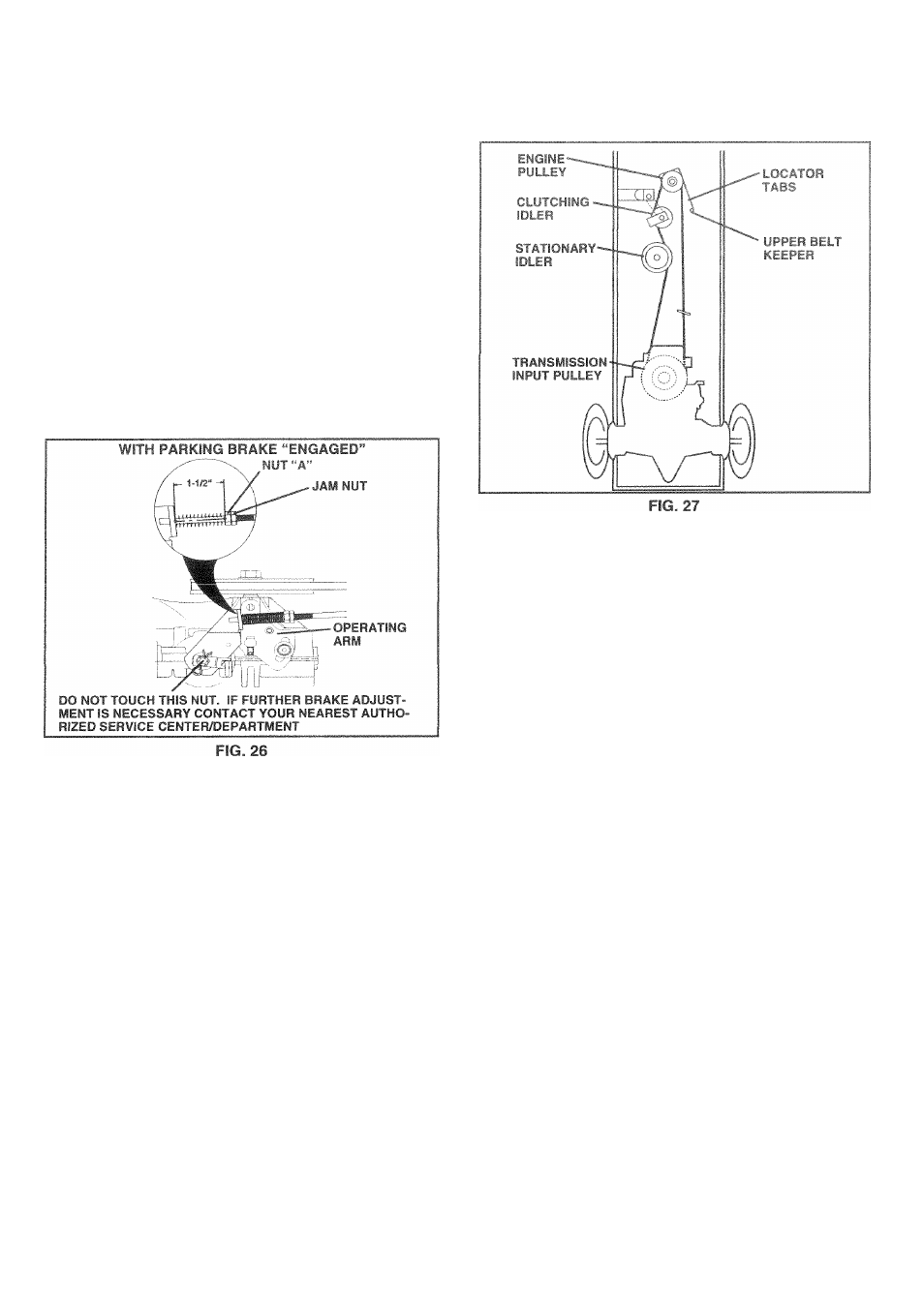
TO REPLACE MOTION DRIVE BELT
(See Fig. 27)
Park the tractor on level surface. Engage parking brake.
For assistance, there is a belt installation guide decal on
bottom side of left footrest.
•
Remove mower (See “TO REMOVE MOWER” in this
section of this manual.)
•
Remove upper belt keeper.
•
Remove belt from stationary idler and clutching idler.
•
Pull belt slack toward rear of tractor. Carefully remove
belt upwards from transmission input pulley and over
cooling fan blades.
•
Pull belt toward front of tractor and remove downward
from around engine pulley.
•
Install new belt by reversing above procedure.
IMPORTANT:
MAKE SURE UPPER BELT KEEPER IS
POSITIONED PROPERLY BETWEEN LOCATOR TABS.
TRANSMISSION REMOVAL/REPLACEMENT
Should your transmission require removal for service or
replacement,
it
should be purged after reinstallation and
before operating
the
tractor. See “PURGE TRANSMIS
SION” in the Operation section of this manual.
TO ADJUST STEERING WHEEL ALIGNMENT
If steering wheel crossbars are not horizontal (left to right)
when wheels are positioned straight
forward,
remove steer
ing wheel and reassemble per instructions in the Assembly
section of this manual.
FRONT WHEEL TOE-IN/CAMBER
The front wheel toe-in and camber are not adjustable on
your tractor. If
damage
has occurred to affect the front
wheel toe-in or camber, contact your nearest authorized
service center/department.
21