2 generator coivipartivients – Generac Power Systems 000595-1 User Manual
Page 25
Attention! The text in this document has been recognized automatically. To view the original document, you can use the "Original mode".
Section 6 - Installation
INSTALLATION
PRIMEPACT 70G
and 70LP Recreational Vehicle Generators
Protect the generator against road splash and debris.
Baffles or splash guards may be required to protect cer
tain ai'eas of the generator. To make sure the generator
is
adequately
protected,
road
test
the
installation
through mud, water and slush.
Figure 6.2
-
Typical
Suspended Mounting
System
GENERATOR MOUNTING
HOLES FOR 3/8" -16
BOLTS (BOTH SIDES)
6.2 GENERATOR COIVIPARTIViENTS
Wlrether the generator set is being installed inside a com
partment specifically manufactured to house a generator
or inside a compartment that the installer constructs, the
compartment MUST meet certain specifications as out
lined in the following sections:
♦ 6.2.1 COMPARTMENT SIZE________________________
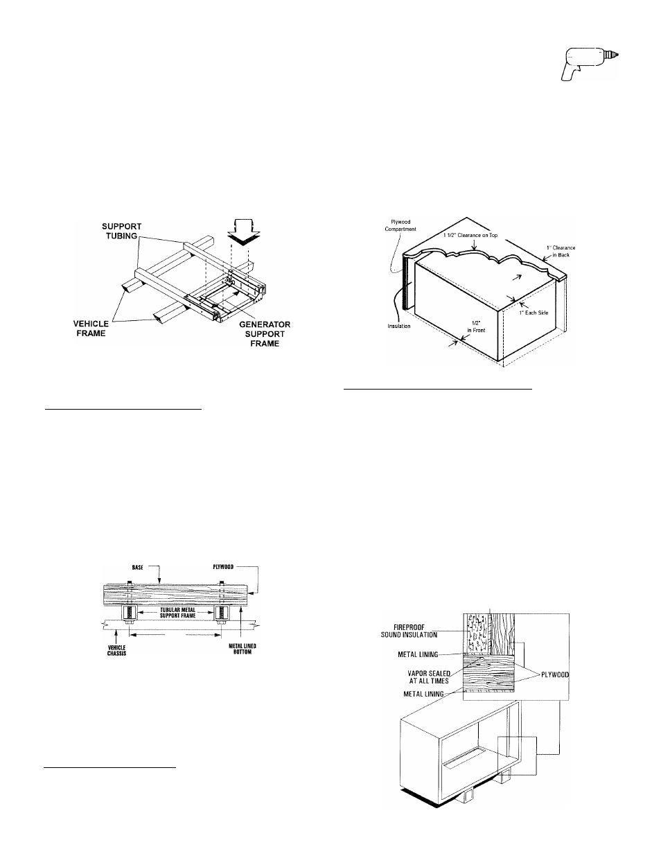
Plan the compartment size carefully. Provide a mini
mum clearance of 1/2 inch (13 mm) on the front and
top, 1 inch (25 mm) on the sides, and 1/2 inch (13 mm)
from ilic back lor air circulation AFTER the compart
ment has been lined with metal and sound insulalioii
(Figure 6.4).
NOTE:
Refer to “Figure 5.2
-
Dimensions” on Page 21.
Major Features and
Figure 6.4
-
Clearances
•
The installer must make certain that the selected
location will permit adequate cooling and ventilating
airflow to be supplied.
♦ 6.1.4
GENERATOR RESTRAINT____________________
Use four 3/8"-16 hardened steel bolts (Grade 5) to fasten
the generator to the supporting frame or the support tub
ing. These bolts must pass through (a) the generator
mounting base, (b) the compartment floor (if a compart
ment
is
used)
and
(c)
the
supporting
framework
(Figure 6.3). /Ml bolts must be long enough so that when
tight, at least three threads are visible past the retaining
lock nuts. Refer to Section 6.2 for the location of the gen
erator mounting holes.
Figure 6.3
-
Typical Generator Restraint
1/2 INCH THICK
• 6.2.2 COMPARTMENT CONSTRUaiON_______________
•
The generator compartment should be either con
structed of, or lined with, 26-gauge galvanized steel.
NOTE:
Aluminum
is
NOT
an
acceptable
alternative
to
galvanized
steel
due
to
aluminum’s
low
melting point.
•
If the compartment is lined with galvanized steel, it
may be constructed of any material. Generac recom
mends that the compartment be constructed of 1/2-
inch thick plywood (not strandboard), with the floor
made of a double thickness of 1/2-inch plywood with
the grain of the wood at cross section for added
strength (Figure 6.5).
Figure 6.5
-
Typical Compartment Construction
CROSS SECTION VIEW
METAL LINING
Generac* Power Systems, Inc. 23