Control valve, Control lever and hydraulic connections, Installation – Troy-Bilt 14066 User Manual
Page 31: Service
Attention! The text in this document has been recognized automatically. To view the original document, you can use the "Original mode".
SERVICE
Control Valve
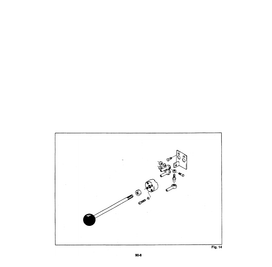
Control Lever and Hydraulic Connections
Install Control linkage as illustrated. Fig. 14.
Install Adaptor Fittings and Quick Disconnect
Couplers.
Note:
1
.
Inspect Adaptor Fitting O Rings and replace
if required.
2. Color Code Rings should be installed to
correspond with Color Code Rings on
Hydraulic Hoses that connect to the Con
trol Valve.
installation
Mount Control Valve on Vai'/e £
Reconnect hydraulic hocas ii>
they were removec.
Note:
2
.
Refer to Hydraulic System :..:ne.nai.c
Diagram to check that hydras.::: ionnec-
tions are correct.
Relief Valve Setting should be adjusted im
mediately following installation sh&rtup as
described under Relief Valve Acjuatment.
Check for hydraulic leaks and ensure hose
routings do not result in hydraulic hoses rubbing
or catching on adjacent tractor/loader com
ponents.