1 unpacking/inspeaion, 5 fuel consumption, 1 unpacking/inspection – Generac DUARDIAN 04077-2 User Manual
Page 6: No alarms are present
Attention! The text in this document has been recognized automatically. To view the original document, you can use the "Original mode".
GENERAL
INFORMATION
Section 1 — G eneral Inform ation
Guardian Air-cooled 6 kW, 8 kW and 10 kW Generators
DANGER
Only qualified electricians or contractors should
attempt such installations, which must comply strictly
with applicable codes, standards and regulations.
1.1
UNPACKING/INSPEaiON
After unpacking, carefully inspect the contents
for damage.
® This standby generator set has been factory sup
plied with a weather protective enclosure that is
intended for outdoor installation only.
* This standby generator set is packaged with an
automatic transfer switch.
® This UL listed, two-pole switch is rated at 100 AC
amperes at 250 volts maximum. This transfer
switch is for indoor use only.
------
M.
WARNING ik----------
A
If this generator is used to power electrical load
circuits normally powered by a utility power
source, you are required by code to install a trans
fer switch. The transfer switch must effectively iso
late the electrical system from the utility distribu
tion system when the generator is operating (NEC
701). Failure to isolate an electrical system by such
means will result in damage to the generator and
also may result in injury or death to utility power
workers due to backfeed of electrical energy.
If any loss or damage is noted at time of delivery,
have the person(s) making the delivery note all
damage on the freight bill or affix his or her signa
ture under the consignor's memo of loss or damage.
If you note loss or damage after delivery, separate
the damaged materials and contact the carrier for
claim procedures.
“Concealed damage” is understood to mean damage
to the contents of a package that is not in evidence
at the time of delivery, but is discovered later.
1.2
PROTECTION SYSTEMS
Unlike an automobile engine, the generator may have
to run for long periods of time with no operator pres
ent to monitor engine conditions. For that reason, the
engine is equipped with the following systems that
protect it against potentially damaging conditions:
1. Low Oil Pressure Sensor 3. Overcrank
2. High Temperature Sensor 4. Overspeed
There are LED readouts on the control panel to
notify you that one of these faults has occurred.
There is also a “System Set” LED that is lit when all
of the following conditions are true:
1. The Auto/Off/Manual switch is set to the AUTO
position.
2. The “Not In Auto” dip switch is set to the OFF
position on the control board.
4 G e n e r a c * P o w e r S y e t e m s , I n c .
3. No alarms are present.
1.3
ADDITIONAL GENERATOR
FEATURES
Your generator offers additional features that are
not factory preset:
1. Remote Start ~ This allows you to remotely start
your generator with the Auto/Off Manual
switch set to AUTO.
2. Remote/Common Alarm - This allows for an
alarm, Ught, hom, etc., to activate when any fault
has occurred.
3. Remote Not Auto - The generator will not auto
matically start during a utility failure.
These options may be set up by your nearest
Generac / Guardian Authorized Dealer.
1.4
FUEL REQUIREMENTS
AND RECOMMENDATIONS
With LP gas, use only the vapor withdrawal
system. This type of system uses the vapors
formed above the liquid fuel in the storage tank.
The engine has been fitted with a fuel carburetion
system that meets the specifications of the 1997
California Air Resources Board for tamper-proof
dual fuel systems. The unit will run on natural gas
or LP gas, but it has been factory set to run on nat
ural gas. Should the primary fuel need to be
changed to LP gas, the fuel system needs to be
reconfigured. See section 1.8 (page 6) for instruc
tions on reconfiguration of the fuel system.
Recommended fuels should have a Btu content of
at least 1,000 Btus per cubic foot for natural gas;
or at least 2,520 Btus per cubic foot for LP gas. Ask
your fuel supplier for the Btu content of your fuel.
Fuel pressure for both natural gas and liquid
propane set ups should be 11 inches to 14 inches
of water column (0.6 psi) at all load ranges.
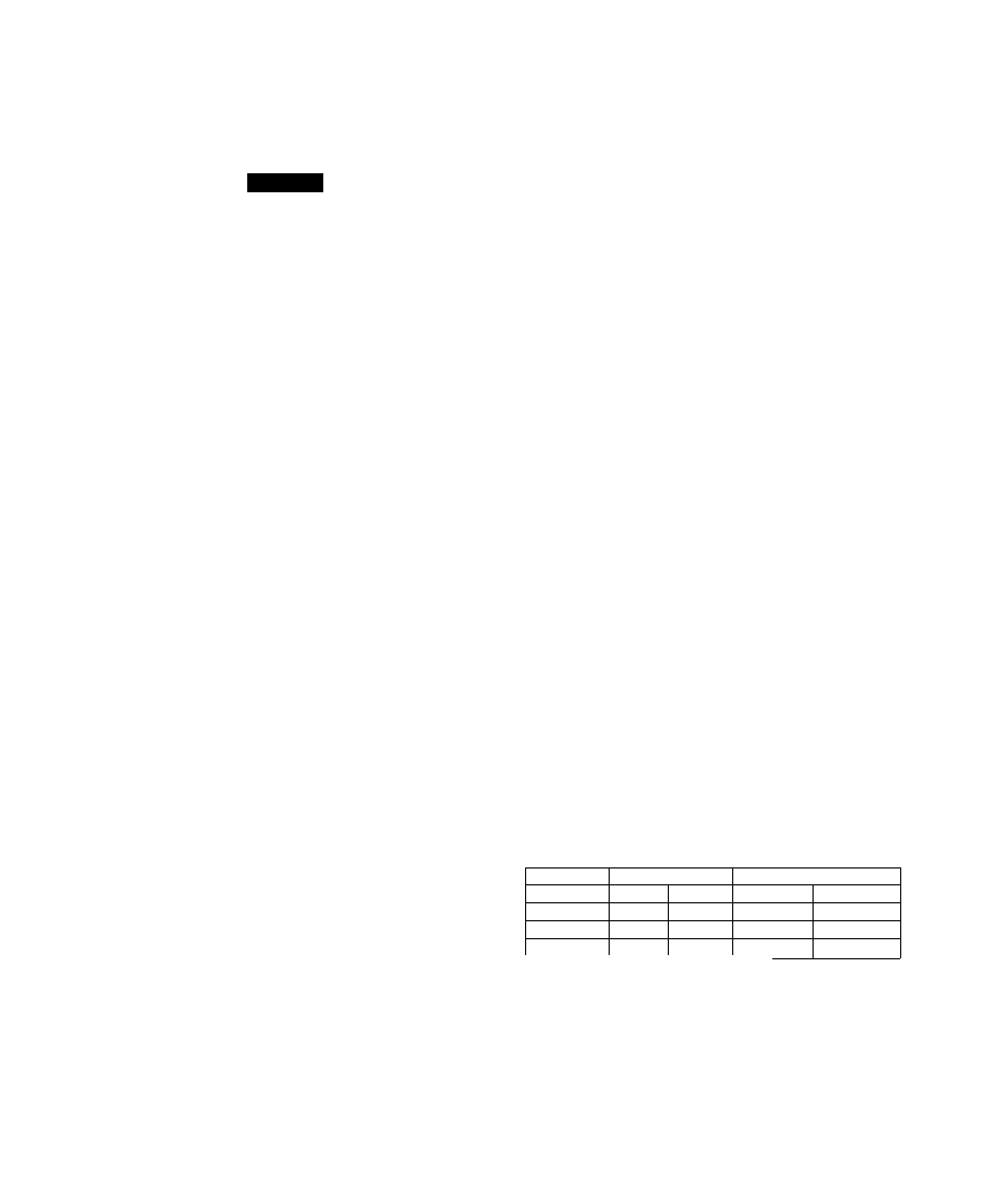
1.5
FUEL CONSUMPTION
Model #
Nat. Gas (*)
LP Vapor (**)
1/2 Load Full Load
1/2 Load
Full Load
04077
(6
kw)
74.1
105.3
0.86/31.30
1.08/39.30
04109 (8 kw)
79.7
140.0
1.07/38.94
1.56/56.77
04079
(10 kw)
100.8
177.9
1.16/42.21
2.15/78.24
*Natural gas is in cubic feet per hour.
**LP is in gallons per hour/cubic feet per hour.
WARNING
Gaseous fuels such as natural gas and liquid
propane (LP) gas are highly explosive. Even the
slightest spark can ignite such fuels and cause
an explosion. No leakage of fuel is permitted.
Natural gas, which is lighter than air, tends to
collect in high areas. LP gas is heavier than air
and tends to settle in low areas.