Generac DUARDIAN 04077-2 User Manual
Page 10
Attention! The text in this document has been recognized automatically. To view the original document, you can use the "Original mode".
OPERATION
Section
2
— O peration
Guardian Air-cooled 6 kW, 8 kW and 10 kW Generators
2.1
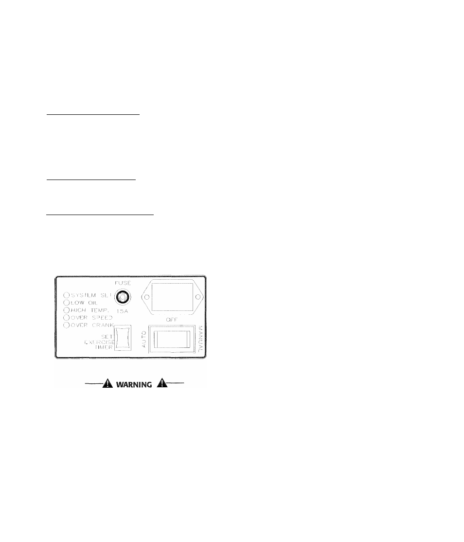
USING THE AUTO/OFF/IVIANUAL
SWITCH
(FIGURE 2.1)
♦ 2.1.1 "AUTO" POSITION________________
Selecting this switch position activates fully auto
matic system operation. It also allows you to start
and exercise the engine every 14 days with the set
ting of the exercise timer (see section 2.5). This
position also is used for remote starting, when it is
set up.
♦ 2.1.2 "OFF" POSITION
____________
This switch position shuts down the engine. This
position also prevents automatic operation.
♦ 2.1.3 "MANUAL" POSITION_____________
Set the switch to MANUAL to crank and start the
engine. Transfer to standby power will not occur
unless there is a utility failure.
Figure
2.1 - Generator Control Panel
With the switch set to AUTO, the engine may
crank and start at any time without warning.
Such automatic starting normally occurs when
utility power source voltage drops below a pre
set level or during the normal exercise cycle. To
prevent possible injury that might be caused by
such sudden starts, always set the switch to
OFF and remove the fuse before working on or
around the generator or transfer switch. Then,
place a "Do Not Operate" tag on the generator
panel and on the transfer switch.
2.2
AUTOIVIATIC TRANSFER
OPERATION
To select automatic operation, do the following:
1. Make sure the transfer switch main contacts
are set to their “Utility” position, i.e., loads con
nected to the utility power source (Figure 2.2).
2. Be sure that normal utility power source voltage
is available to transfer switch terminal lugs N1
and N2.
3. Set the generator’s Auto/Off/Manual switch to
AUTO.
4. Set the generator’s main circuit breaker to its
ON (or closed) position.
With the preceding steps complete, the generator
will start automatically when utility source voltage
drops below a preset level. After the unit starts,
loads are transferred to the standby power source.
Refer to “Sequence of Automatic Operation.”
2.3
SEQUENCE OF
AUTOMATIC OPERATION
The generator’s control panel houses a control logic
circuit board. This board constantly monitors utili
ty power source voltage. Should that voltage drop
below a preset level, circuit board action will signal
the engine to crank and start. After the engine
starts, the circuit board signals the transfer switch
to activate and connect load circuits to the standby
power supply (load terminal lugs
T1/T2
connect to
terminal lugs E1/E2).
Upon restoration of utility source voltage above a
preset level, generator circuit board action signals
the transfer switch to transfer loads back to that
power supply. After retransfer, the engine is sig
nalled to shut down.
The actual sequence of operation is controlled by
sensors and timers on a control logic circuit board,
as follows:
A. Utility Voltage Dropout Sensor
• This sensor monitors utility source voltage.
• If utility source voltage drops below about 60
percent of the nominal supply voltage, the sen
sor energizes a 15-second timer.
® Once the timer has expired, the engine will
crank and start.
B. Engine Warm-up Time Delay
• This mechanism lets the engine warm up for
about 10 seconds before the load is transferred
to a standby source.
C. Standby Voltage Sensor
« This sensor monitors generator AC output volt
age. When the voltage has reached 50 percent
of the nominal rated voltage, transfer to stand
by can occur.
Generac* Power Systems, Inc.