Service and ad.iiisti»4efs'r – Poulan 160464 User Manual
Page 21
Attention! The text in this document has been recognized automatically. To view the original document, you can use the "Original mode".
SERVICE AND AD.IiiSTi»4EfS'r-^
IT i
Adjust tli6 mowsr whif
0 trsctor is psrkscf on l©¥s! QrouncJ or
t o i , r * i v r
'
di"" r ' ' I u
I I ^ f-
"PRODUCT SPECIFICATIONS” on page 2 of this manual).
If tires are over or underinflated, you will not properly adjust
yuui
1 1
luvvei.
Sir- ‘ i'T -[Ml '
^ -id 19)
•
P'-jise mow L-. li- h.uhtst t- j-ition
•
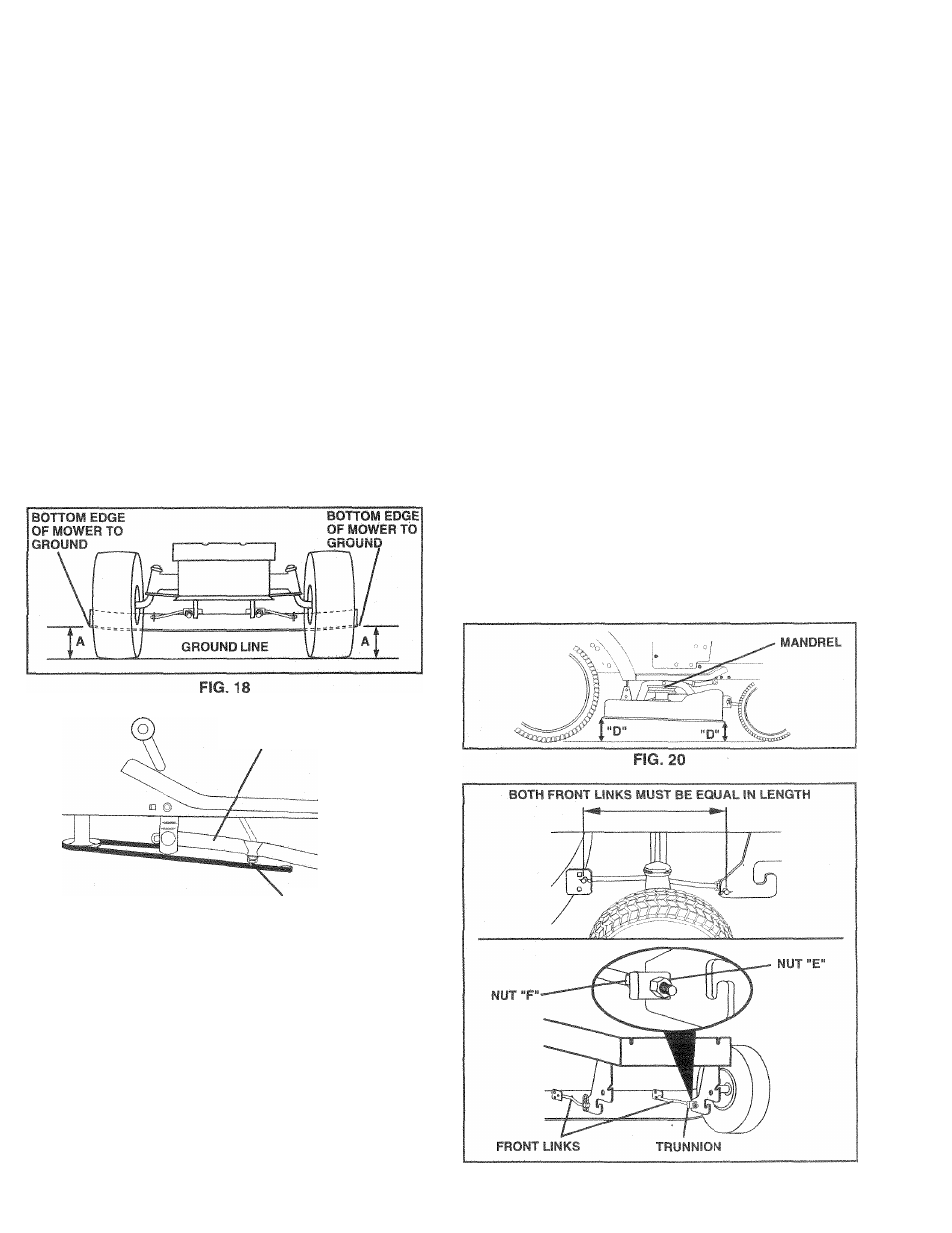
At the nidpu nl uJ -oth side.- o- mower measure height
from bottom edge of mo /srto ground Distance “A” on
uurti side-. "I
ifiowt.
:ujid
be
ihe c.ame tr within 1/4"
fj each _thcr
•
IT ad uotnent i- no- or, rn-te :djii*^iRtrnt on one
side
of
rruwe.
only
•
To raise one side of mower, tighten lift link adjustment
nut on that side.
•
To lower one side of mower, loosen lift link adjustment
nut on that side.
NOTE: Three full turns of adjustment nut will change
mower height about 1/8".
•' Recheck measurements after adjusting.
SUSPENSION ARM
LIFT LINK
ADJUSTMENT NUT
FIG. 19
U I R P T O .
iTH F
) MC ¡VVER WILL STA'
Y
LEVEL SIDE
best cutting results, t he rfiowe r hoL
steels,o that the front is approximat
eiy 1/
1
the rear when the mo wer is in f is hia
iure dis-
t bottom
lents, check that
h links should be
IMPORTANT:
I
THE FOLLOWl
NECESSARY, E
EQUALLY
SIDE.
To obtain
should bee
|)0 lit! ■!
Checl" ooju i/t'e a ih I 'U -
‘
i‘.
t a p c e i i fly
. .
s
r
1
edge n ^ - ■ r h.i m' .g ; ■ r
•
Before making any necessary adji
botl
1
ti
If!
i' JU y' . I - i ‘.
cippiC V‘t ia'( I' f (H
» It link ■ - lenuth .»hi ti'f'' » To inwei f.oiit t)‘ .I'lwu l i > j ' l I't.i “E" cu both irurl links a' -quel i»oTiber cf lurtis • When Oiatarice D la ' A »o b_" L'Wer ui fiont thcii real, tighten nuts F ag-nnm trjr.r i,-»n on both from • To raise front of mower, loosen nut “F” from trunnion on both front links. Tighten nut “E” on both front links an • When distance “D” is 1/8" to 1/2“ lower at front than rear, tighten nut “F” against trunnion on both front links. • Recheck side-to-side adjustment. 21 FIG. 21
links.
equal number of turns.