Attaching the clutch cable – MTD 315B User Manual
Page 5
Attention! The text in this document has been recognized automatically. To view the original document, you can use the "Original mode".
Hex Bolts, Flat
Upper Handle washers and Nuts
jpport
racket
Lou^ Handle
FIGURE 4.
M /
Lociv ,
/ Nuts
(
FIGURE 5.
Drive
ATTACHING THE CHIPPER CHUTE AND
SUPPORT BRACKET
(See figure 4)
1. Remove the two hex lock nuts from the hex bolts
which secure the right side of the upper handle to
the lower handle. Leave bolts and washers in
place.
2. Remove three cupped washers and 5/16" hex
nuts from the weld studs beside the opening on
the right side of the chipper-vacuum.
3. Place the chipper chute in position over the weld
studs (slot goes at the bottom). Secure with
cupped washers and hex nuts just removed. Only
tighten the three nuts one or two threads for ease
of further assembly.
NOTE:
Cupped side of the washer goes against the
chipper chute. See figure 2 to identify cupped side of
washer.
4
. Remove the two hex bolts, flat washers and nuts
which are attached to the support bracket.
5. Attach the support bracket to the bottom of the
chipper chute loosely using the hardware
removed previously. HEADS OF THE HEX
BOLTS AND WASHERS GO TO THE INSIDE OF
THE CHIPPER CHUTE.
6. Place the support bracket over the two bolts in
the handle. Pushing UP on the chipper chute will
aid the alignment of the holes in the support
bracket with the bolts in the handle.
7. Tighten all hardware securely on the chipper
chute, support bracket and handle.
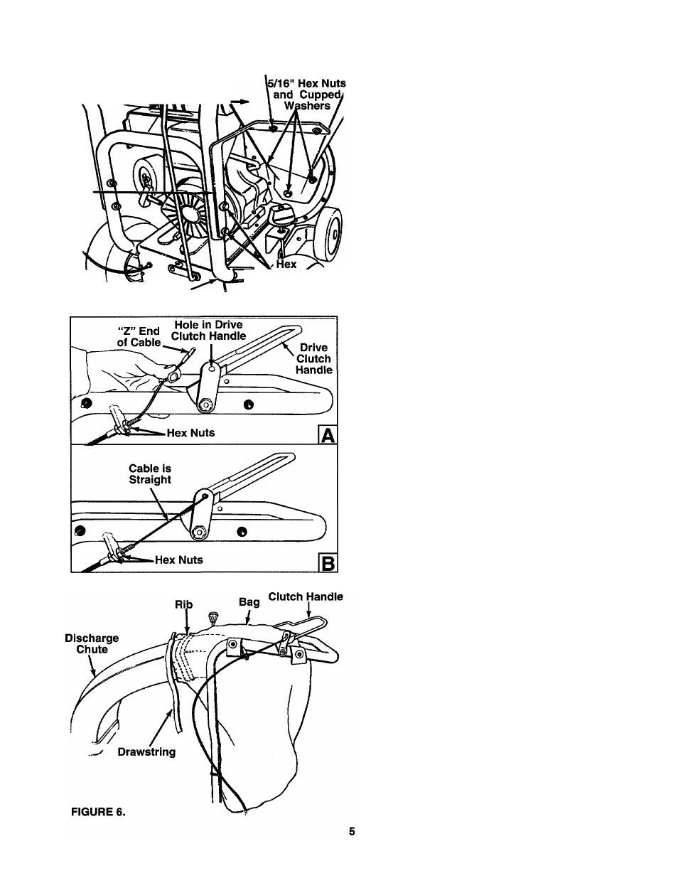
ATTACHING THE CLUTCH CABLE
The clutch cable has been assembled at the factory.
Loosen the hex nuts at the cable bracket. Hook the
“Z” end of the cable into the drive clutch handle from
the outside to the inside as shown in figure 5A. Pliers
will aid in assembly.
CLUTCH CABLE ADJUSTMENT
Adjust the hex nuts at the cable bracket so there is no
slack in the cable, but the
cable is NOT tight. Do not
overtighten the cable.
See figure 5B.
To check the clutch adjustment, proceed as follows.
1. Push the chipper-vacuum backward and forward
with the drive clutch handle released. It should
move freely.
If it does not, loosen both hex nuts at the cable
bracket. See figure 5B. Turn bottom nut counter
clockwise to loosen the cable.
2. Engage the drive clutch handle (hold against
upper handle), and try to push chipper-vacuum
backward and forward. The wheels should lock
up.
If the wheels do not lock up, loosen both hex nuts
at the cable bracket. Turn bottom nut clockwise to
tighten the cable.
3. Recheck adjustment. Tighten both hex nuts when
correct adjustment is reached.