Flexible pump coupler, Tire pressure, Installation of tire to rim – MTD 242-632-000 User Manual
Page 12: Off-season storage
Attention! The text in this document has been recognized automatically. To view the original document, you can use the "Original mode".
The
spark plug
should be cleaned and the gap reset
once
a
season.
Spark
plug
replacement
is
ecom-
mended
at
the
start
of
each
season;
check
engine
manual for correct plug type and gap specificat on.
Clean the engine
regularly with a cloth or brush.
Keep the cooling system (blower housing area) clean
to
permit
proper
air
circulation
which
is
esseitial
to
engine performance and life. Be certain to rerr ove all
dirt and combustible debris from muffler area.
PUMP
FLEXIBLE PUMP COUPLER
The flexible pump coupler is a nylon “spider” insert,
located
between
the
pump
and
engine
sha
't.
The
alignment is very critical. Over a period of tine, the
coupler will harden and deteriorate. For a re place
ment
flexible
pump
coupler,
order
part
number
717-
0891.
IMPORTANT:
Never hit the pump shaft in
anf
man
ner, as any blow will cause permanent damage to the
pump.
When
replacing
the
flexible
pump
coupling,
p
oceed
as follows.
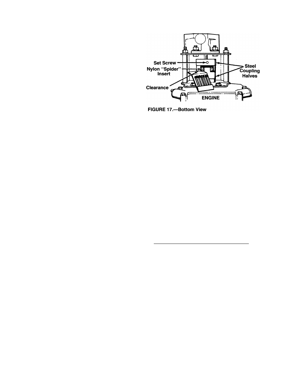
1.
Place the coupling half onto the engine shaft.
Make certain there is clearance between tf e cou
pling half and the engine. Tighten the set screw.
2.
Mount the pump onto the coupling support brack
et. Tighten securely.
3.
Carefully
slide
coupling
half
onto
pump
shaft
(make certain set screw is loose). Slide tie key
into place on the shaft.
4.
Install the nylon “spider” insert into coupling half
on the engine shaft.
5.
Place the coupling shield in position on the hex
bolts. Rotate the keyway on the pump shaft so it
is toward the bottom.
6
.
Attach the coupling support bracket to the hex
bolts, carefully sliding the coupling half o\ er the
“spider”
insert.
Secure
coupling
shield
and
cou
pling support bracket with lock washers and hex
nuts. Tighten securely.
7.
Adjust the two coupling halves (steel) so t lere is
between
.
010
”
and
.060”
clearance
between
the
two halves (at least the thickness of a matchbook
cover,
up
to
1/16”
maximum).
See
figure
17.
Tighten the set screw in the coupling half on the
pump shaft.
NOTE:
Make certain proper clearance is ob tained
before tightening set screw.
TIRE PRESSURE
Check
sidewall
of
tire
for
manufacturer’s
recommend
ed maximum tire pressure. If this information does not
appear on your tire, maximum tire pressure under any
circumstances
is
30
p.s.i.
Equal
pressure
should
be
maintained on both tires.
INSTALLATION OF TIRE TO RIM
A
WARNING: The following procedure must
be followed when removing or installing
a tire to the rim.
1. Be certain rim is clean and free of rust.
2. Lubricate both the tire and rim generously.
3.
Never inflate to over 30 p.s.i. to seat beads.
Excessive
pressure
when
seating
beads
may
cause tire/rim assembly to burst with force suffi
cient to cause serious injury.
OFF-SEASON STORAGE
If the log splitter will not be used for a period longer
than 30 days, the following steps should be taken to
prepare the log splitter for storage.
1.
Clean the engine and the entire log splitter thor
oughly.
2.
Refer to the engine manual for correct engine
storage
instructions.
Follow instructions care
fully.
3.
Wipe unit with an oiled rag to prevent rust, espe
cially wedge and beam.
4.
Store unit in a clean, dry area. Do not store next
to corrosive materials, such as fertilizer.
NOTE:
When storing any type of power equipment in
an unventilated or metal storage shed, care should be
taken to rustproof the equipment by coating with a
light oil or silicone.
12