Figures, Operation – MTD 241-645A User Manual
Page 5
Attention! The text in this document has been recognized automatically. To view the original document, you can use the "Original mode".
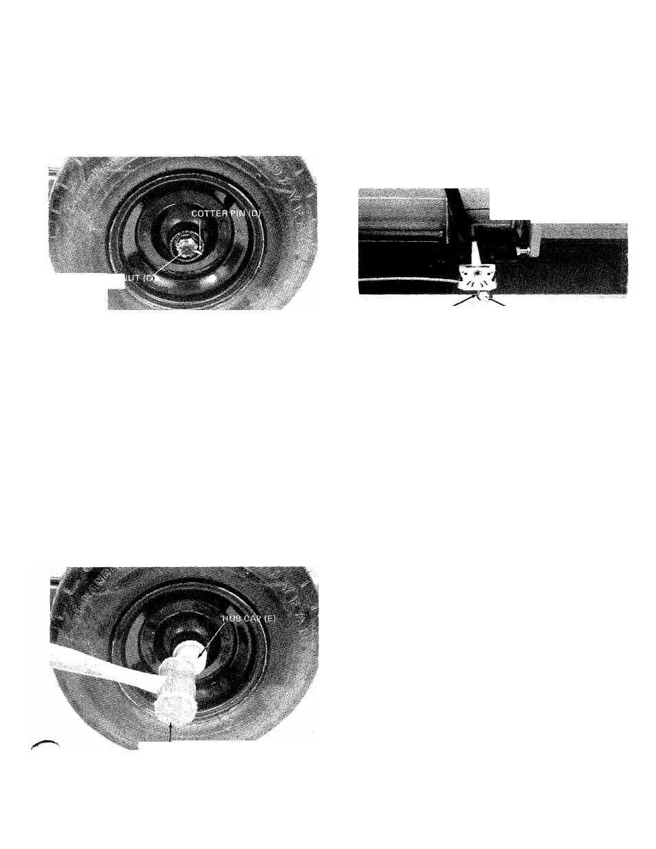
3. Thread hex castle nut (C) on axle. Tighten castle
nut until snug, back off approximately 1/3 turn
or until one of the slots on the castle nut lines up
with hole in axle. Secure castle nut to axle with
cotter pin (D). See figure 3.
5. Repeat steps 1 through 4 for the second wheel.
6. Secure engagement handle to beam with shoulder
bolt (F) and flat washer (G).See figure 5.
HEX CASTL
ENGAG^ENT HANDLE
FLAT WASHER (G)
^SHOULDER BOLT (E)
ENGAGEMENT ROD HAIR PIN COTTER
-FERRULE
WlblMI KUU
M
1 /
FIGURES
4. Place hub cap (E) in position on wheel and tap on
with a plastic hammer. See figure 4.
FIGURES
HAMMEri
7. Remove the hair pin cotter from ferrule.
8. Secure engagement rod to engagement handle
with hair pin cotter. See figure 5.
OPERATION
FIGURE 4
1. Service engine with gas and oil. See engine manual
packed with log splitter for complete instructions
for the care and maintenance of engine. READ
DIRECTIONS CAREFULLY.
2.
Fill fuel tank with one gallon of regular grade
gasoline. See figure 6.
3. Engine will require 1-1/2 pints jif SAE 30 or
10W30 oil. Remove oil dipstick. See figure 6.