Cleaning the generator, Bahery, Service and adjustments – Generac Power Systems 00802-3 User Manual
Page 13: Throhle linkage adjustment, Cleaning the generator battery
Attention! The text in this document has been recognized automatically. To view the original document, you can use the "Original mode".
CLEANING THE GENERATOR
Keep your generator set as clean and dry as possible.
Dirt and moisture that are permitted to accumulate on
electrical windings have an adverse affect on the
insulation resistance of those windings.
Moisture that is allowed to remain in contact with wind
ings will be retained in voids and cracks of the wind
ings. Dirt makes the problem worse, since it tends to
hold the moisture into contact with the windings. Salt,
as from sea air, worsens the problem since it tends to
absorb moisture from the air. The combination of salt
and moisture makes a good electrical conductor.
CAUTION! Do NOT use a forceful spray of water to
clean the generator. Water will enter the generator
interior and cause probiems, and may also conta
minate the generator fuel system.
BAHERY
All lead-acid storage batteries will discharge when not
in use. Inspect the generator battery as follows:
■ ONCE WEEKLY_______________________
Inspect battery posts and cables for tightness, corro
sion. Clean and/or tighten as necessary.
Also check battery fluid level, and, if necessary, fill
with DISTILLED WATER ONLY. DO NOT USE TAP
WATER IN BATTERY.
■ EVERY SIX MONTHS___________________
Have the battery state of charoe and condition
checked by an automotive service facility. This should
be done with an automotive type battery hydrometer.
DANGER; Storage batteries give off explosive
hydrogen gas. This gas can form an explosive
mixture around the battery for several hours after
charging. The siightest spark can ignite the gas
and cause an explosion. Such an expiosion can
shatter the battery and cause biindness or other
injury. Any area that houses a storage battery
must be properly ventilated. Do not allow smok
ing, open flame, sparks or any spark producing
tools or equipment near the battery.
DANGER; Battery electrolyte fluid is an extremely
caustic sulfuric acid solution that can cause
severe burns. Do not permit fiuid to contact eyes,
skin, clothing, painted surfaces, etc. Wear protec
tive goggies, protective clothing and gloves when
handling a battery. If you spill the fluid, fiush the
affected area immediately with clear water.
DANGER; Do not use any jumper cables or boost
er battery to crank and start the generator engine.
If any battery has discharged, remove it from the
vehicle for recharging.
SERVICE AND ADJUSTMENTS
■ ENGINE SPEED_________________________
Engine
speed
is
completely
computer-controlled.
There is no adjustment for speed on the unit. The
computer adjusts the engine speed using an electron
ic governor throttle control. The computer monitors
the demand for power and adjusts the engine speed
accordingly. This allows the engine to produce only
the power required, resulting in fuel economy as well
as lowering the overall noise emitted.
NOTE:
The computer will disable the electrical load
capabilities of the generator and enter a fault condi
tion if you accelerate the throttle manually or any
other way.
THROHLE LINKAGE ADJUSTMENT
If needed, you can adjust the length of the linkage rod
between the electronic governor lever arm and the
carburetor throttle lever arm. This adjustment helps to
establish the proper travel relationship between the
two lever arms. I
t
this adjustment is not properly set,
the computer will NOT have control of the full range of
engine speed. If the rod adjustment is set too snort,
the computer will not have access to wide open throt
tle or “full power" conditions. If the rod adjustment is
set too long, the computer will not have access to
closed throttle or “no power” conditions.
Use the following procedure to assure the linkage rod
is properly adjusted;
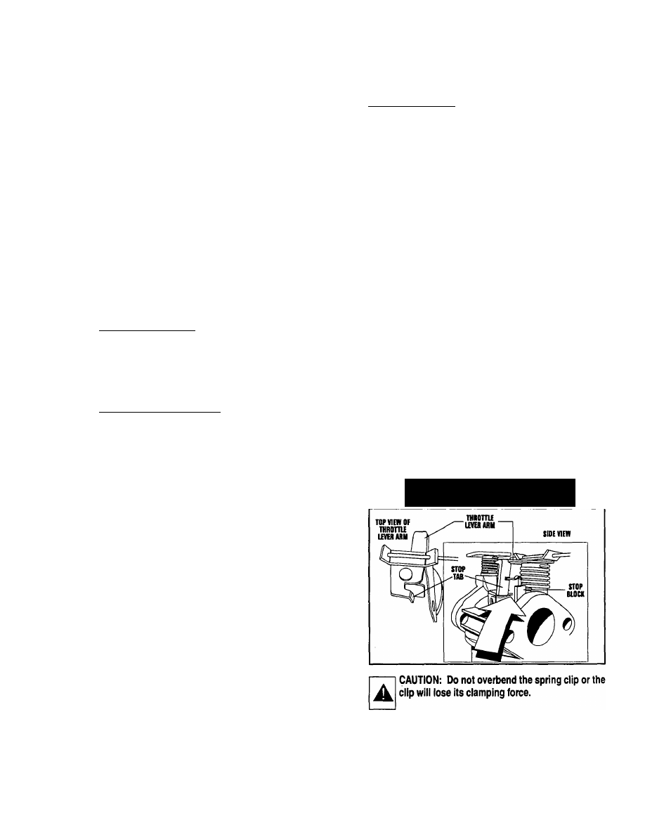
1. Start the generator, then shut it down right away. As the
engine coasts to a stop, observe from above the engine
as the throttle lever on the carburetor rotates counter
clockwise.
2. There should be a gap of 0.003 inch (0.08-0.5mm)
between stop tab on throttle lever arm and the stop block
on the carburetor die casting (Figure 9).
Figure 9 — Gap Between Stop Tab
and Stop Block
—11
—