Note – MTD 249-645A User Manual
Page 7
Attention! The text in this document has been recognized automatically. To view the original document, you can use the "Original mode".
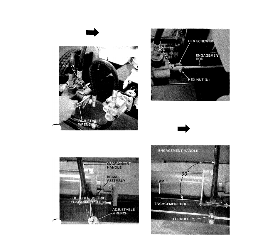
9. Secure the other end of high pressure hose to
valve. A 3/4" wrench is required. See figure 9.
11. Place end of engagement rod on valve spool and
secure with hex screw (M) and hex nut (N).
See figure 11.
NOTE
Use hydraulic sealant tape on threads.
HIGH PRESSURE
HOSE
FIGURE 9
10.
Assemble the engagement handle to the beam
assembly using shoulder bolt (K) and flat washer
(L). A 3/4" wrench is required. See figure 10.
FIGURE 11
12. Thread ferrule (O) on engagement rod so there is
approximately
1/2"
of
thread
showing.
Engagement handle must be at 90° to beam. Insert
ferrule into engagement handle. See figure 12.
NOTE
Engagement handle locked in reverse
position must depress valve spool to
limit.
FIGURE 10
FIGURE 12
- 24642-8 (16 pages)
- 648D (12 pages)
- 247-640A (12 pages)
- 246-604-000 (14 pages)
- 245-642-000 (16 pages)
- 241-521-000 (18 pages)
- 244-595-000 (12 pages)
- 462 thru 465 (28 pages)
- 462 thru 465 (16 pages)
- 552 (20 pages)
- TBLE (1 page)
- 24595-A (12 pages)
- 243-600 (6 pages)
- 242-610-000 (12 pages)
- 249-623-003 (19 pages)
- 244-647C000 (10 pages)
- TBPS (44 pages)
- 24645-A (12 pages)
- 245-638-000 (7 pages)
- 246-641A000 (12 pages)
- 246-638-000 (7 pages)
- 243-645B000 (12 pages)
- 243-630-000 (20 pages)
- 243-636-000 (20 pages)
- 24650-A (12 pages)
- 24650S (12 pages)
- 510 (20 pages)
- 24596S (12 pages)
- 24650-9 (16 pages)
- 242-648-000 (12 pages)
- 244-648D401 (12 pages)
- 243-638-000 (20 pages)
- 24650U (12 pages)
- 645C thru 650C (12 pages)
- 242-635A (14 pages)
- 245596C (12 pages)
- 244-638-000 (16 pages)
- 243-640A000 (12 pages)
- 639 (16 pages)
- 245-632-000 (12 pages)
- 247-462B000 (4 pages)
- 24632C (10 pages)
- 24650-8 (16 pages)
- Duerr 248-622-003 (16 pages)
- 462 thru 464 (20 pages)