MTD 249-645A User Manual
Page 6
Attention! The text in this document has been recognized automatically. To view the original document, you can use the "Original mode".
5. Repeat steps 1 through 4 for the second wheel.
6.
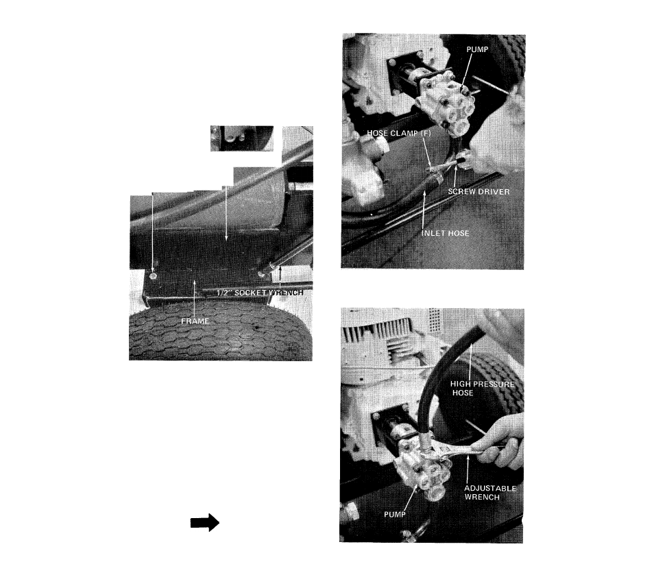
With help from another person, place beam
assembly on frame and line up four holes, secure
with four hex screws (H), lock washers (I) and
hex nuts (J). See figure 6. Two 1/2" wrenches or
socket is required.
1
BEAM ASSEMBLY
HEX SCREW (A)
LOCKWASHER (I)
HEX IMUT (J)
FIGURE 6
7.
Secure the inlet hose to the pump with hose
clamp (F), provided in hardware pack. A standard
screwdriver is required. See figure 7.
8.
Assemble the high pressure hose to the pump. A
1-1/8" wrench or adjustable wrench is required.
See figure 8.
NOTE
Use hydraulic sealant tape or pipe sealant
on threads.
FIGURE 7
FIGURES
- 24642-8 (16 pages)
- 648D (12 pages)
- 247-640A (12 pages)
- 246-604-000 (14 pages)
- 245-642-000 (16 pages)
- 241-521-000 (18 pages)
- 244-595-000 (12 pages)
- 462 thru 465 (28 pages)
- 462 thru 465 (16 pages)
- 552 (20 pages)
- TBLE (1 page)
- 24595-A (12 pages)
- 243-600 (6 pages)
- 242-610-000 (12 pages)
- 249-623-003 (19 pages)
- 244-647C000 (10 pages)
- TBPS (44 pages)
- 24645-A (12 pages)
- 245-638-000 (7 pages)
- 246-641A000 (12 pages)
- 246-638-000 (7 pages)
- 243-645B000 (12 pages)
- 243-630-000 (20 pages)
- 243-636-000 (20 pages)
- 24650-A (12 pages)
- 24650S (12 pages)
- 510 (20 pages)
- 24596S (12 pages)
- 24650-9 (16 pages)
- 242-648-000 (12 pages)
- 244-648D401 (12 pages)
- 243-638-000 (20 pages)
- 24650U (12 pages)
- 645C thru 650C (12 pages)
- 242-635A (14 pages)
- 245596C (12 pages)
- 244-638-000 (16 pages)
- 243-640A000 (12 pages)
- 639 (16 pages)
- 245-632-000 (12 pages)
- 247-462B000 (4 pages)
- 24632C (10 pages)
- 24650-8 (16 pages)
- Duerr 248-622-003 (16 pages)
- 462 thru 464 (20 pages)