Strainer tube assembly, Note, Pressure relief valve setting – MTD 249-645A User Manual
Page 13: To set the pressure relief valve, Engine maintenance
Attention! The text in this document has been recognized automatically. To view the original document, you can use the "Original mode".
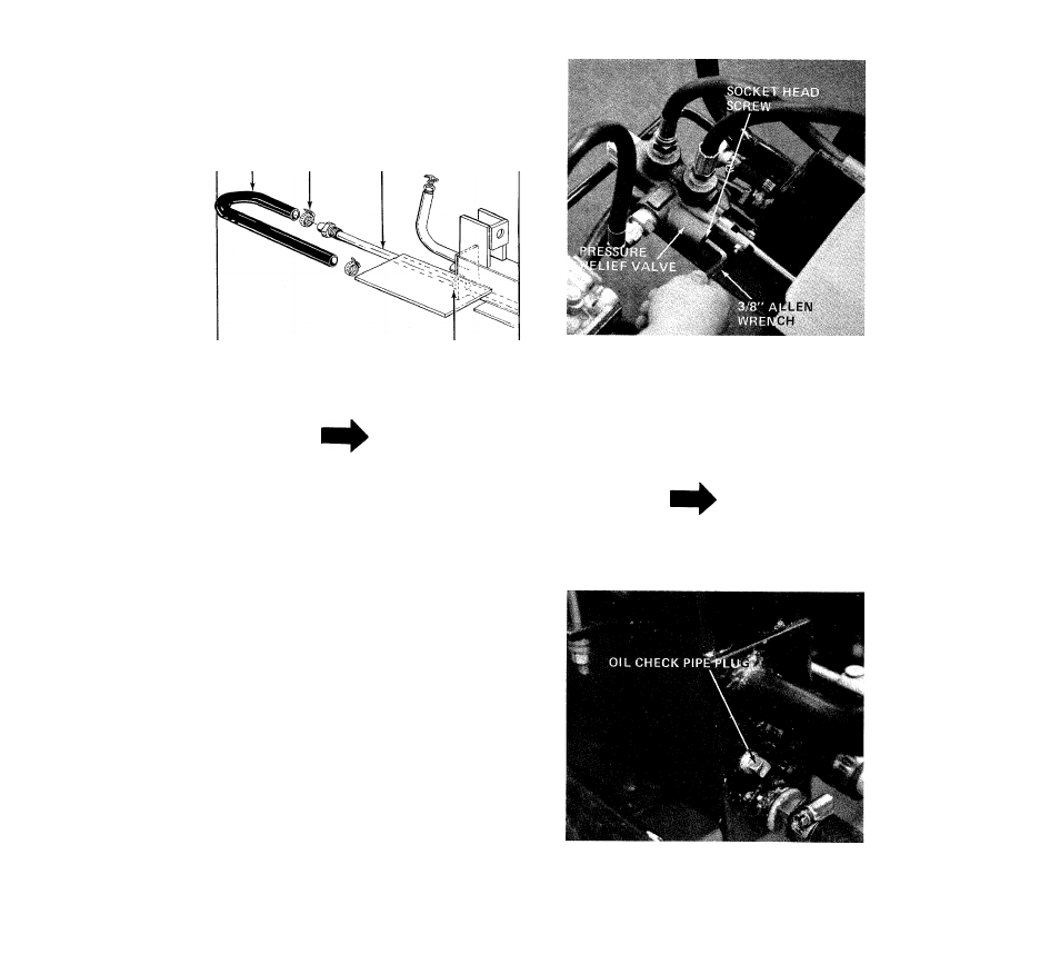
3. With an adjustable wrench remove the strainer
tube assembly. See figure
21.
INLET HOSE
HOSE CLAMP
STRAINER TUBE
ASSEMBLY
BOTTOM HOLE ON
BEAM ASSEMBLY
FIGURE 27
NOTE
The strainer tube assembly is 53" long.
4.
Clean and reassemble using a hydraulic pipe
sealant on the threads.
PRESSURE RELIEF VALVE SETTING
If the pressure relief valve is set too low it will open up
before enough pressure is built up to properly operate
the ram. See figure 28.
TO SET THE PRESSURE RELIEF VALVE
1. Have someone place a log crossways in the Splitter
and allow the Ram to push against it with the
engine running wide open.
If the engine begins to lug down, the Relief Valve
setting is correct.
3.
If adjustment is necessary, tighten the screw until
the engine begins to lug down.
FIGURE 28
Check o^il in log splitter reservoir before every use.
See figure 29.
1.
Block up front of log splitter so beam is setting
level.
2.
Remove check pipe plug in rear of beam. See
figure 29. If oil starts to come out of check pipe
plug hole oil level is correct. IF NOT add oil to
breather tube (figure 16) unit oil starts out.
NOTE
Use hydraulic sealant tape or pipe
sealant on pipe plut threads.
3.
Replace check pipe plug, remove block from
under front of beafn.
FIGURE 29
ENGINE MAINTENANCE
13 REFER TO ENGlKlE MANUAL.