Section i, General information and assembly, 1. technical description – MTD 1850 User Manual
Page 4: 2. preliminary preparation, 3. assembly, Note, A. ' heel and wheel hanger assembly, Technical description -1, Preliminary preparation -1, Assembly -1
Attention! The text in this document has been recognized automatically. To view the original document, you can use the "Original mode".
SECTION I
GENERAL INFORMATION AND ASSEMBLY
1-1. TECHNICAL DESCRIPTION
The
Model
1850
Rotary
Tiller
is
equipped
wih
a
Briggs and Stratton 8 hp, 4-cycle engine and a recoil
starter. The tines are heavy duty slasher type and the
wheels are 10 x 2.50 inches with a rib tread. This til
ler weighs 340 pounds.
The maximum tilling width is 26 inches.
1-2. Preliminary Preparation
Maximum
tilling
results,
equipment
performance,
and
personal
safety
depend
on
correct
operation
of
the equipment and on proper maintenance of its com
ponents.
The
operator
of
this
Penncraft
rotary
tiller
should,
therefore,
famiarize
himself
with
the
machine
and
its
controls
before
attempting
to
operate
the
equipment. The two important considerations are:
a.
Knowing
the
location
of
each
control
and
its
function,
as
outlined
in
this
manual,
to
ensure
for most efficient operation of the equipment and
for best performance.
b.
Observing
the
operating
instructions
and
safety
rules at all times to prevent possible injury to
persons and to equipment.
1-3. Assembly
The
Model
1850
is
shipped
completely
assembleo
except for the handle, depth bar, and wheels. These
parts, with the necessary hardware, are easily assem
bled to the machine, as outlined in this section.
NOTE
Reference
to
right-hand
or
left-hand
side of machine is from the operating
position.
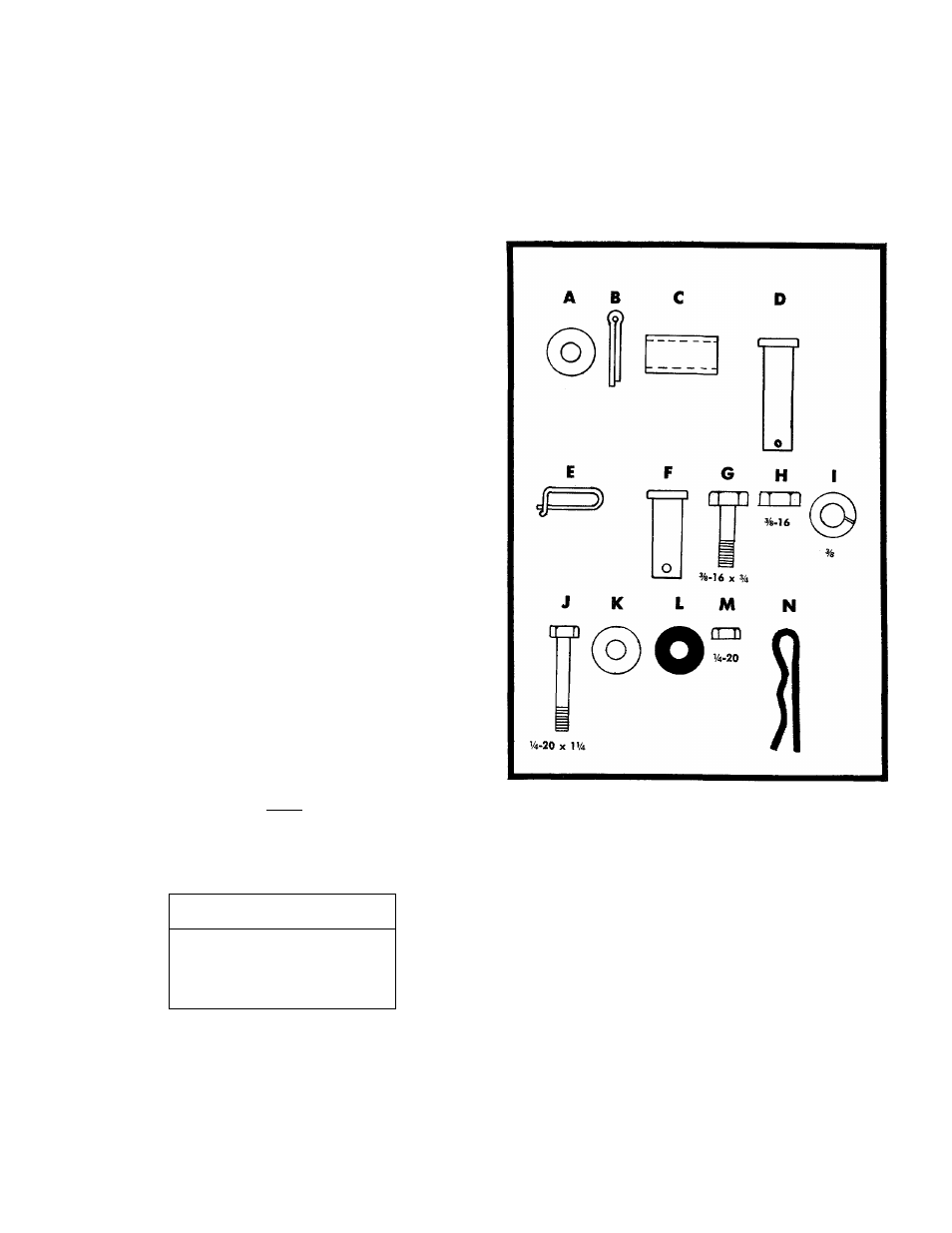
HARDWARE SUPPLIED
TOOLS NEEDED
Two
7/16" Wrenches
Two
9/16" Wrenches
a. ' heel and Wheel Hanger Assembly
Refer to figure 1-1.
Step 1. Slide the axle through the wheel hanger.
Step 2. Place the washer A, spacer C, wheel, and
washer A on each side of the axle and secure
each with a cotterpin B.
1-1