MTD 1850 User Manual
Page 14
Attention! The text in this document has been recognized automatically. To view the original document, you can use the "Original mode".
Step 3. Place your foot on the rear of the depth bar
and apply pressure. The belts will go slack.
Step 4. Remove the REAR belt first and ALLOW IT TO
FORM
A
LOOP
AROUND
THE
VARIABLE
SPEED PULLEY.
Step 5. Slide the center section of the variable-speed
pulley towards the engine. See Figure 4-7.
Step 6. Remove the FORWARD belt from the engine
pulley and the variable-speed pulley.
NOTE
By following this order of belt removal,
it is not necessary to remove the belt
guard on the varible-speed pulley.
Step 7. Remove the rear belt from the variable-speed
pulley.
Step 8. Reassemble with the new belts.
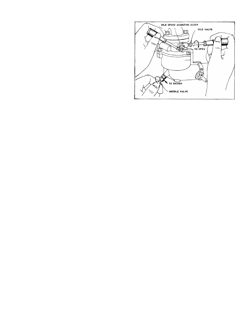
FIGURE 4-9. CARBURETOR ADJUSTMENT
4-n. ADJUSTING THE CARBURETOR
Minor
carburetor
adjustment
may
be
required
to
compensate
for
differences
in
fuel,
temperature,
alti
tude and load.
To Adjust Carburetor:
Turn needle valve clockwise until it just closes. See
Figure 4-9.
CAUTION
Valve may be damaged by turning it in
too far.
Now open needle valve IV
2
turns counter-clockwise.
Close idle valve in same manner and open
V
a
to %
turns. This initial adjustment will permit the engine to
be started and warmed up prior to final adjustment.
Final Adjustment;
Turn needle valve in until engine misses (lean mix
ture) then turn it out past smooth operating point until
engine
runs
unevenly
(rich
mixture).
Now
turn
needle
valve to the mid-point between rich and lean so the en
gine runs smoothly.
Hold throttle at idle position and set idle speed ad
justing screw until fast idle is obtained (1750 RPM).
Hold
throttle
in
idle
position
and
turn
idle
valve
in
(lean) and out (rich) until engine idles smoothly. Then
reset idle speed adjusting screw so that engine idles
at
1750
RPM.
Release
throttle—engine
should
accel
erate
without
hesitation
or
sputtering.
If
engine
does
not
accelerate
properly,
the
carburetor
should
be
re
adjusted to a slightly richer mixture.
4-12. ADJUSTING CARBURETOR CHOKE
Proper choke and stop switch operation is depend
ent upon proper adjustment of remote controls on the
powered equipment.
To Check The Operation Of The Choke:
Step 1. Remove the air cleaner.
Step 2. Pull the throttle control all the way out to the
CHOKE
position.
See
Figure
2-1.
The
choke
should be closed.
Step 3. The engine should shut off when the throttle
control is all the way in. (STOP position.)
To Adjust;
Place
remote
control
lever
on
equipment
in
FAST
(high
speed)
position.
Loosen
control
casing
clamp
screw "B." Move control casing "A" and wire until lever
"D" touches choke operating link at "C." Tighten cas
ing clamp screw "B." Replace air cleaner. See Figure
4-10.
4-4