To stop engine, Figure 17, Carburetor adjustment – MTD 241-675-000 User Manual
Page 7: Clutch rod adjustment, Adjustments, Height adjustment, Maintenance, Lubrication
Attention! The text in this document has been recognized automatically. To view the original document, you can use the "Original mode".
3. Crank engine by pulling recoil starter with a quick,
firm stroke. Do not pull out so far the rope stops
with a jerk. Do not allow rope and handle to snap
back into place.
4. After two or three full firm pulls on recoil (or as soon
as engine fires), move choke control to RUN
position.
5.
Self-Propelled Models Only—
To engage the
drive mechanism, squeeze the clutch grip against
the upper handle. Release the clutch grip to stop
the forward motion.
TO STOP ENGINE
1. To stop engine, move throttle control lever to OFF
position.
2. Disconnect spark plug wire and ground to prevent
accidental starting while equipment is unattended.
IMPORTANT:
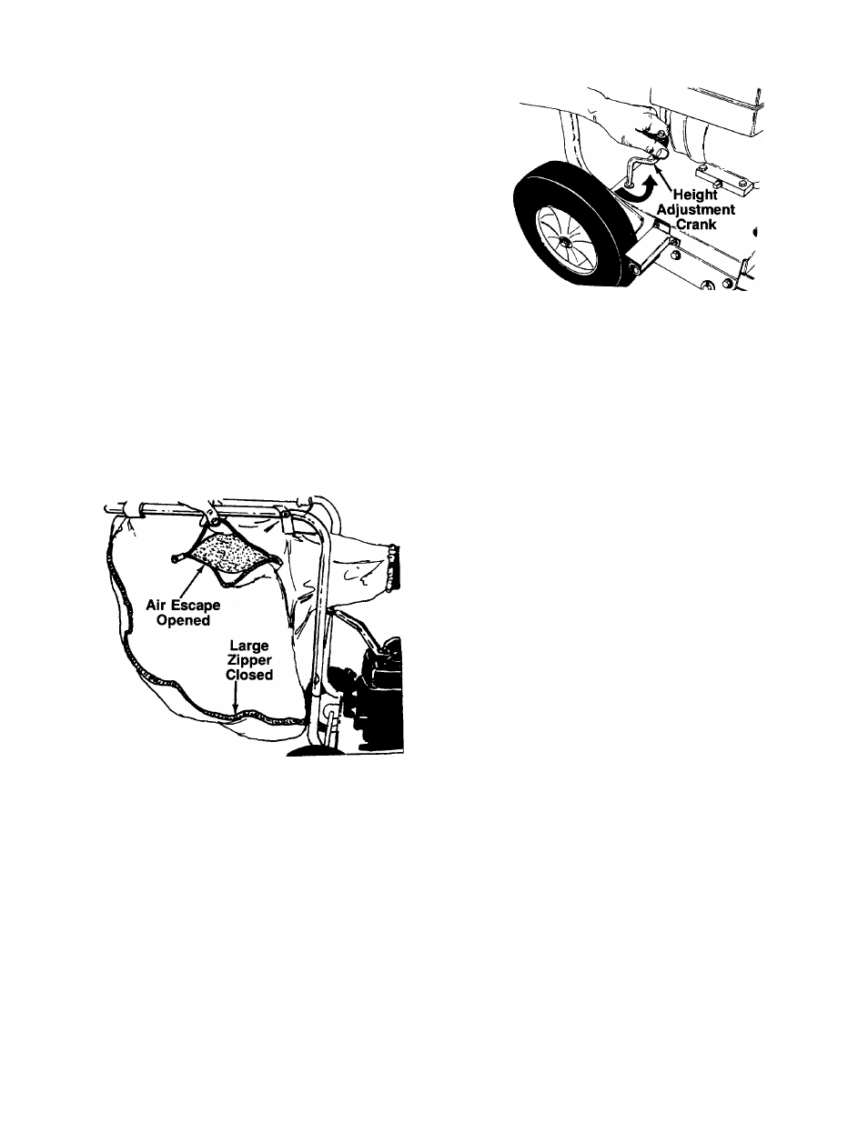
The vacuum bag may have an air
escape located on the upper right hand side. See figure
16. The air escape can be opened if the vacuum is
operated in wet, sandy or muddy conditions.
FIGURE 17.
CARBURETOR ADJUSTMENT
A
WARNING: If any adjustments are made to
the engine while the engine is running
(e.g. carburetor), keep clear of all moving
parts. Be careful of heated surfaces and
muffler.
FIGURE 16.
Minor carburetor adjustment may be required to com
pensate for differences in fuel, temperature, altitude or
load.
NOTE:
A dirty air cleaner will cause engine to run rough.
Be certain air cleaner is clean and attached to the car
buretor before adjusting carburetor.
Do not make unnecessary adjustments. Factory settings
are satisfactory for most applications and conditions.
If adjustment is needed, refer to the separate engine
manual packed with your vacuum.
CLUTCH ROD ADJUSTMENT
(Self-Propelled Models Only)
To adjust the clutch rod, refer to step numbers 3 and
4 under “Attaching the Clutch Rod” in Assembly In
structions.
ADJUSTMENTS
A
WARNING: Do not at any time make any
adjustment to the unit without first stop
ping engine and disconnecting spark plug
wire.
HEIGHT ADJUSTMENT
The height adjustment crank is located on the right
hand side of the vacuum. See figure 17. Turn the crank
clockwise to raise the nozzle. Turn the crank counter
clockwise to lower.
MAINTENANCE
A
WARNING: Always stop engine and
disconnect spark plug wire before clean
ing, lubricating or performing any repairs
or maintenance.
LUBRICATION
Wheels—
Rear wheels are provided with lite oil bear
ings. Place a few drops of SAE 30 oil on each bearing
once a season.