Citizen Systems iDP-3423 User Manual
Page 53
iDP-3420/3421/3423 User’s Manual
53
CITIZEN
11111111.... D
D
D
DR
R
R
RA
A
A
AW
W
W
WE
E
E
ER
R
R
R K
K
K
KIIIIC
C
C
CK
K
K
K----O
O
O
OU
U
U
UT
T
T
T C
C
C
CO
O
O
ONN
NN
NN
NNE
E
E
EC
C
C
CT
TT
TO
O
O
OR
R
R
R
11111111....1111 SSSSppppeeeecccciiiiffffiiiiccccaaaattttiiiioooonnnns
s
s
s oooof
f
f
f D
D
D
Drrrraaaaw
w
w
weeeer
r
r
r K
K
K
Kiiiicccckkkk----O
O
O
Ouuuut
t t
t C
C
C
Coooonn
nn
nn
nneeeeccccttttoooorrrr
(1) Drawer kick-out drive signal
Parallel ----- Can be learned at the no. 34 pin of the interface connector
Serial ----- Provided with a command to learn the status in the STAR and ESC/POS modes.
(2) Electrical characteristics
1) Drive voltage: 24 V DC
2) Drive current: 0.8 A at maximum (Within 510 ms)
3) Switch signal: Signal level
"L" = 0 to 0.5 V
"H" = 3 to 5 V
11111111....2222 C
C
C
Coooonn
nn
nn
nneeeeccccttttoooorrrr''''s
s
s
s P
PP
Piiiin
n
n
n C
C
C
Coooonnnnffffiiiigggguuuurrrraaaattttiiiioooonnnn
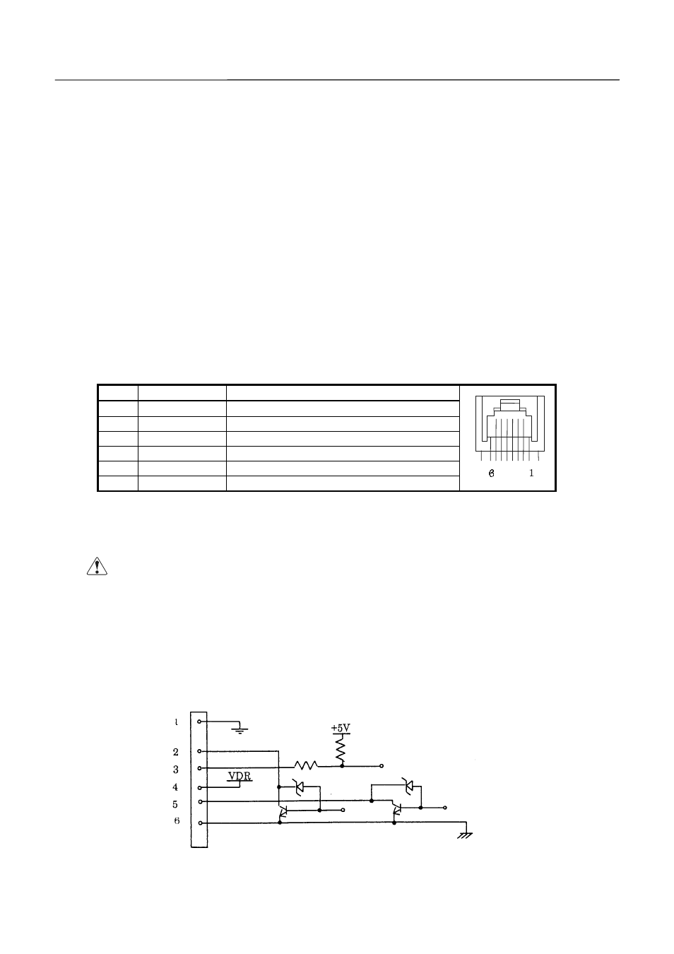
No.
Signal
Function
1
FG
Frame Ground
2
DRAWER 1
Drawer 1 drive signal
3
DRSW
Drawer switch input
4
VDR
Drawer drive power
5
DRAWER 2
Drawer 2 drive signal
6
GND
Common ground on the circuit
Connector used
: TM5RJ3-66 (HIROSE)
Applicable connector : TM3P-66P (HIROSE) or equivalent
C
C
C
CA
A
A
AU
U
U
UT
TT
TIIIIO
O
O
ON
N
N
N
: · No output is made while printing.
· The drawers 1 and 2 cannot be driven simultaneously.
· A solenoid used for the drawer should be of 36W or more. An output current
should be kept below 0.8 A. Use beyond this limit cannot be assured.
· This connector cannot be connected to a telephone line. Do not connect
other than the solenoid.
11111111....3333 D
D
D
Drrrriiiivvvve
e
e
e C
C
C
Ciiiirrrrccccuuuuiiiitttt