Adjustments/ maintenance, Ii j, Replacement of friction wheel — continued – Ariens 932007 User Manual
Page 8: Belt replacement - general — figures 8 & 9, Replacement of traction drive belt — figures 3 & 9, Figure 8, Figure 9
Attention! The text in this document has been recognized automatically. To view the original document, you can use the "Original mode".
ADJUSTMENTS/ MAINTENANCE
REPLACEMENT OF FRICTION WHEEL — CONTINUED
8.
Replace the bearing flange on the right side of the frame
and secure with the four carriage bolts and nuts. Recon
nect the traction clutch rod in the clutch fork arm and
secure with a hairpin cotter. Readjust the traction clutch
as
described
in
“TRACTION
CLUTCH
ADJUSTMENT”
section.
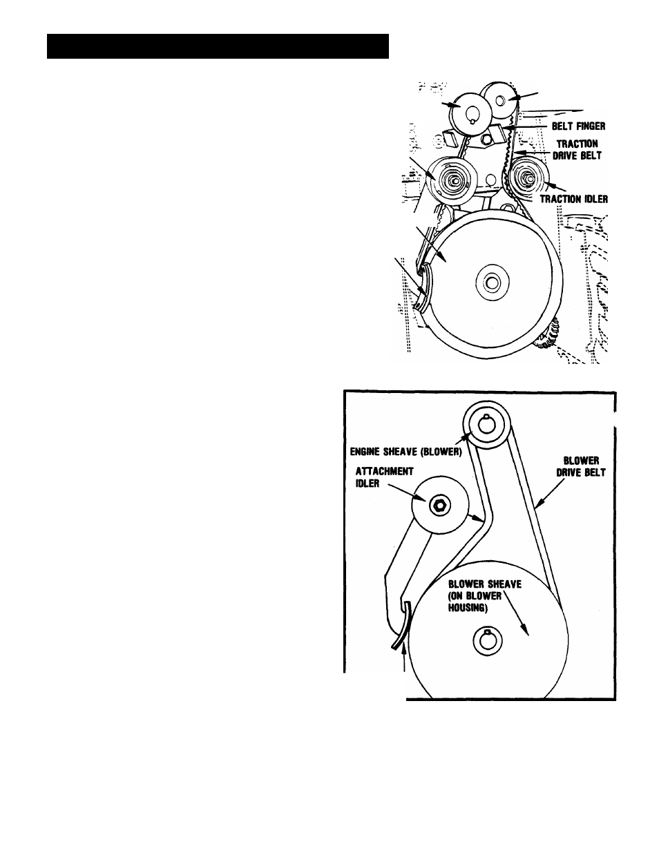
BELT REPLACEMENT - GENERAL — FIGURES 8 & 9
CAUTION:
SINCE
REPUCING
THE
BELTS
WILL
INVOLVE
TURN
ING THE ENGINE OVER WITH THE STARTER, AND THE ENGINE
MIGHT
ACCIDENTALLY
START
RESULTING
IN
INJURY.
THE
SPARK
PLUG
WIRE
MUST
BE
DISCONNECTED
DURING
THIS
PROCEDURE.
The traction drive belt and the blower drive belt are both accessi
ble by tipping apart the blower housing and tractor as follows:
1.
Remove the nut and lockwashers holding the worm clevis
on the bracket. Remove the chute crank by sliding it back
in the bracket and out of the way.
2.
Remove the two screws securing the belt guard to the trac
tor. Remove belt guard.
3.
Remove the top screws and loosen the lower screws on
each side that secures the blower housing to the frame. As
the blower housing and tractor are tipped apart, roll the
blower belt off the engine sheave between the sheave and
belt finger. This can be easily done by pulling the recoil
starter rope to rotate the engine sheave. See “CAUTION”
note,this section. With the blower belt disconnected, the
blower housing may then be tipped from the frame.
REPLACEMENT OF TRACTION DRIVE BELT — FIGURES
3 & 9
CAUTION:
SINCE
REPLACING THE
BELTS
WILL INVOLVE TURN
ING THE ENGINE OVER WITH THE STARTER, AND THE ENGINE
MIGHT
ACCIDENTALLY
START
RESULTING
IN
INJURY,
THE
SPARK
PLUG
WIRE
MUST
BE
DISCONNECTED
DURING
THIS
PROCEDURE.
With the blower and tractor tipped apart, pull the idler away from
the traction drive belt and remove belt from around the traction
sheave and engine sheave. Install the new belt on the engine
sheave and traction sheave. Then reposition the idler back into
position on the outside of the traction drive belt.
With the belts in position and the idler in place, check the belt
alignment. The engine sheave and the tractor sheave must align
with one another. If the sheaves are not properly aligned, loosen
the setscrews on the engine sheave and align the sheaves.
Retighten the setscrews.
ENGINE
SHEAVE
(BLOWER)
ENGINE SHEAVE
(TRACTION)
AHACHMENT
IDLER
TRACTION SHEAVE
^ ii J
BRAKE SHOE J
FIGURE 8
BRAKE SHOE
FIGURE 9
- 8