Assembly & pre-service, General, Handlebar installation - figure 13 – Ariens 932007 User Manual
Page 13: Wiring harness - figure 13, Traction clutch rod - figure 13, Figure 13a
Attention! The text in this document has been recognized automatically. To view the original document, you can use the "Original mode".
ASSEMBLY & PRE-SERVICE
WARNING:
FAILURE
TO
FOLLOW
ALL
INSTRUCTIONS
FOR
ASSEMBLY
AND
PRE-SERVICE
COULD
RESULT
IN
PERSONAL
INJURY
AND/OR
DAMAGE
TO
THE
SNO-THRO.
CHECK
AND
TEST
THE
FUNCTION
OF
ALL
CONTROLS
BEFORE
STARTING
ENGINE AND BE SURE TO FILL ENGINE WITH OIL.
WARNING:
ALL
ASSEMBLY
AND
ADJUSTMENT
PROCEDURES
ARE TO BE MADE WITH ENGINE STOPPED AND SPARK PLUG
WIRE DISCONNECTED.
NOTE: MAKE SURE ALL SAFETY DEVICES AND GUARDS ARE IN
POSITION
AND
OPERATING
PROPERLY.
READ
THE
OWNER’S
MANUAL
AND
ITS
INSTRUCTIONS
FOR
SAFE
OPERATION
BEFORE USING UNIT.
GENERAL
The unit is shipped with tractor and snow head assembled. The
handlebars are assembled but must be installed, along with the
clutch rods and chute crank.
HANDLEBAR INSTALLATION - FIGURE 13
The handlebars are attached to the holes in the side of the frame.
Install a cap screw (59022, 3/4” long), a flat washer (64123)
and lockwasher (63003) in the lower holes on each side of the
^^handle and attach to the frame. Do not tighten. Insert a cap
^ icrew (59069,1-1 /4” long), a washer (64123) and lockwasher
t63003) through each of the upper holes in the handlebars. Hold
the handlebars up in a comfortable position and tighten all hard
ware. The handlebars are adjustable for customer use.
WIRING HARNESS - FIGURE 13
The wiring harness is supplied attached to the engine. Run this
harness from the engine, up the left handlebar, to the key
switch. Connect wire to terminals on the key switch; wires can
be attached to either terminal. Secure the wiring harness to the
left handlebar with clamp (69099).
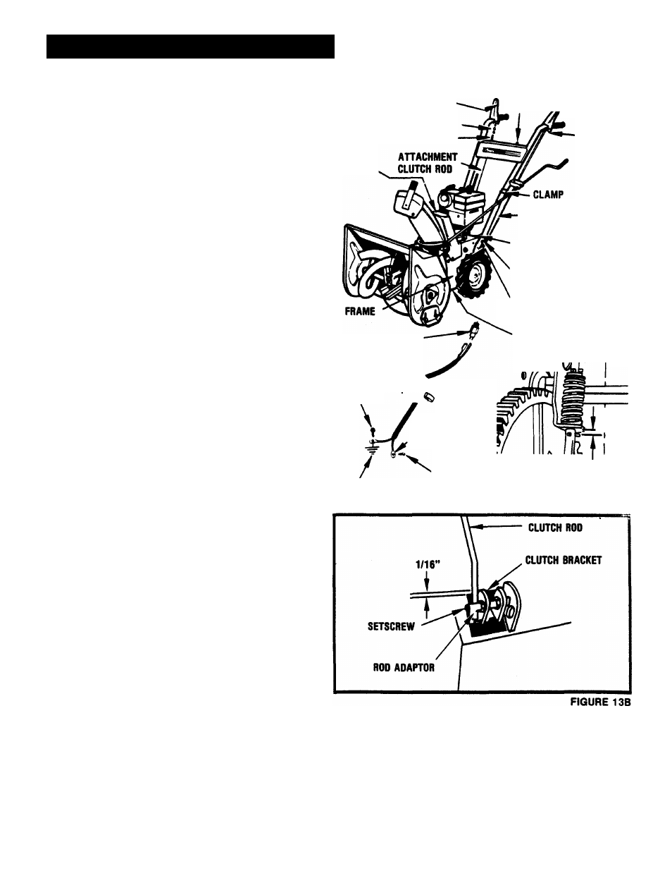
TRACTION CLUTCH ROD - FIGURE 13
The traction clutch rod is shipped loose in the carton. To install
the rod, place the Speed Selector in third speed; insert the bent
end of the clutch rod into the hole in the clutch handle on the left
handlebar. See Figure 13A. Insert the straight end of the clutch
rod into the hole in the rod adapter in the clutch bracket at the
left rear of the frame. See Figure 13B. Hold the clutch handle all
the way down; raise the clutch bracket up to 1/16 inch of the
frame; now tighten the rod in place with the setscrew in the rod
adapter.
This adjustment can be checked by tipping Sno-Thro onto blower
housing and removing bottom cover. To remove bottom cover,
^^remove the two screws on each side of cover that mount it to the
ame. With the clutch handle fully depressed the clearance bet
ween the roll pin and the bracket should be 1/8 inch to 3/16
inch. See Figure 13A. Loosen the setscrew and readjust if re
quired.
AHACHMENT
CLUTCH HANDLE
CHAIN
SPRING
KEY
SWITCH
BELT
COVER
TRACTION
CLUTCH ROD
TRACTION
CLUTCH
HANDLE
-(BENT
END OF
CLUTCH
ROD
GOES
HERE)
KEY
SWITCH
ON PANEL
FLANGE
WHIZLOCK
SCREW
WIRE HARNESS
1-1/4” CAP SCREW
IN UPPER HOLE
3/4” CAP SCREW
IN LOWER HOLE
BOnOM
COVER
TO
FRAME
CLAMP
TO ENGINE
MAGNETO
1/8” T0Í
3/16’
TAPPING
SCREW
FIGURE 13A
-
13