Step 3: installing the throttle lever, Step 4: assembling and installing the cutter bar, À caution – Troy-Bilt 31/2 HP User Manual
Page 10: Step
Attention! The text in this document has been recognized automatically. To view the original document, you can use the "Original mode".
EASY ASSEMBLY
Step 3: Installing the Throttle Lever
1. The throttle cable is already attached to the Throt
tle Lever and the carburetor. Unwrap the throttle cable
and lever from the mower.
2. From underneath the control panel, insert the
Throttle Lever’s handle up, through the small rectan
gular cut-out in the control panel.
3. From above the control panel, insert one of the
#10-32 X Vz-inch screws down through one of the
cut-outs in the control panel decal. Make sure that
this screw goes through the hole in the base of the
Throttle Lever. Loosely install one of the #10 lock-
washers and one of the #10-32 nuts on this screw.
4. Install the second screw, lockwasher, and nut in
the remaining hole. Then tighten both nuts with a
%-inch wrench and screwdriver.
Photo 2-4: Installing the throttle lever.
5. Move the Throttle Lever forward and backward
several times. If the lever binds or does not have full
travel, loosen both nuts that you installed in Steps 3
and 4. From underneath the control panel, push the
base of the Throttle Lever slightly to the right.
Retighten both nuts and again check the Throttle
Lever for free movement. If the Throttle Lever should
still not move, push the carburetor's throttle arm
(where the lower end of the Throttle Lever cable is
secured) to the left. (Occasionally dried paint on the
throttle arm pivot keeps it from moving.)
6. Place the Throttle Lever knob on top of the Throttle
Lever handle. Use a piece of wood to gently tap the
knob onto the Throttle Lever handle.
Step
4: Assembling and Installing the Cutter Bar
À CAUTION
The cutter blades are sharp. Keep the plastic
blade protector on the cutter bar when working
on or near the cutter bar.
Failure to do so could result in personal injury
or property damage.
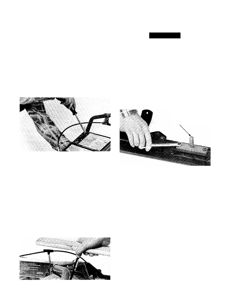
1. If the drive pin is not installed on the cutter blade,
place it on top of the blade. Align the holes in the
base of the drive pin with the holes in the cutter bar.
Secure the drive pin in place with two 8 MM x 25 MM
bolts and two 8 MM lockwashers. Use a 13 MM (or a
Vz-inch) wrench to evenly and securely tighten both
bolts. See Photo 2-6.
APPLY
GREASE
8
Photo 2-5; Installing the throttle lever knob.
Photo 2-6: Installing the drive pin.
2. Grasp the drive pin with one hand. Steady the cut
ter bar with your other hand. Try to move the cutter
blade from side to side. Occasionally dried paint will
prevent the blade from moving. If you can’t move the
blade, rap the side of the drive pin with a rubber mal
let to break the cutter blade free of the dried paint.
3. Place the drive socket on the drive pin. Place the
cutter bar assembly in front of the mower's nose
piece.
4. Lubricate the drive pin with multi-purpose grease.
5. Have an assistant push down on the handlebars to
very slightly raise the nose of the mower.
6. Slowly slide the cutter bar assembly rearward.
Make sure that; a) the cutter bar mount rests on top
of the cutter bar and its four holes align with the four
(square) holes in the cutter bar mount, and b) the
shaft on the drive socket enters the hole in the front
of the drive arm.
7.
From underneath, insert a 5/16-18 x VA-inch car
riage bolt up through one of the holes in the cutter
bar. Loosely install a 5/16-18 nut on this bolt. Repeat