Fig. 2-2: assemble handlebar, Fig. 2-3: wheel in freewheeling position, Attach the handlebar – Troy-Bilt 12065 User Manual
Page 9: Move tiller off shipping platform
Attention! The text in this document has been recognized automatically. To view the original document, you can use the "Original mode".
NOTE: “LEFT” and “RIGHT”
sides of tiller are as viewed from
the operator’s position behind the
handlebars.
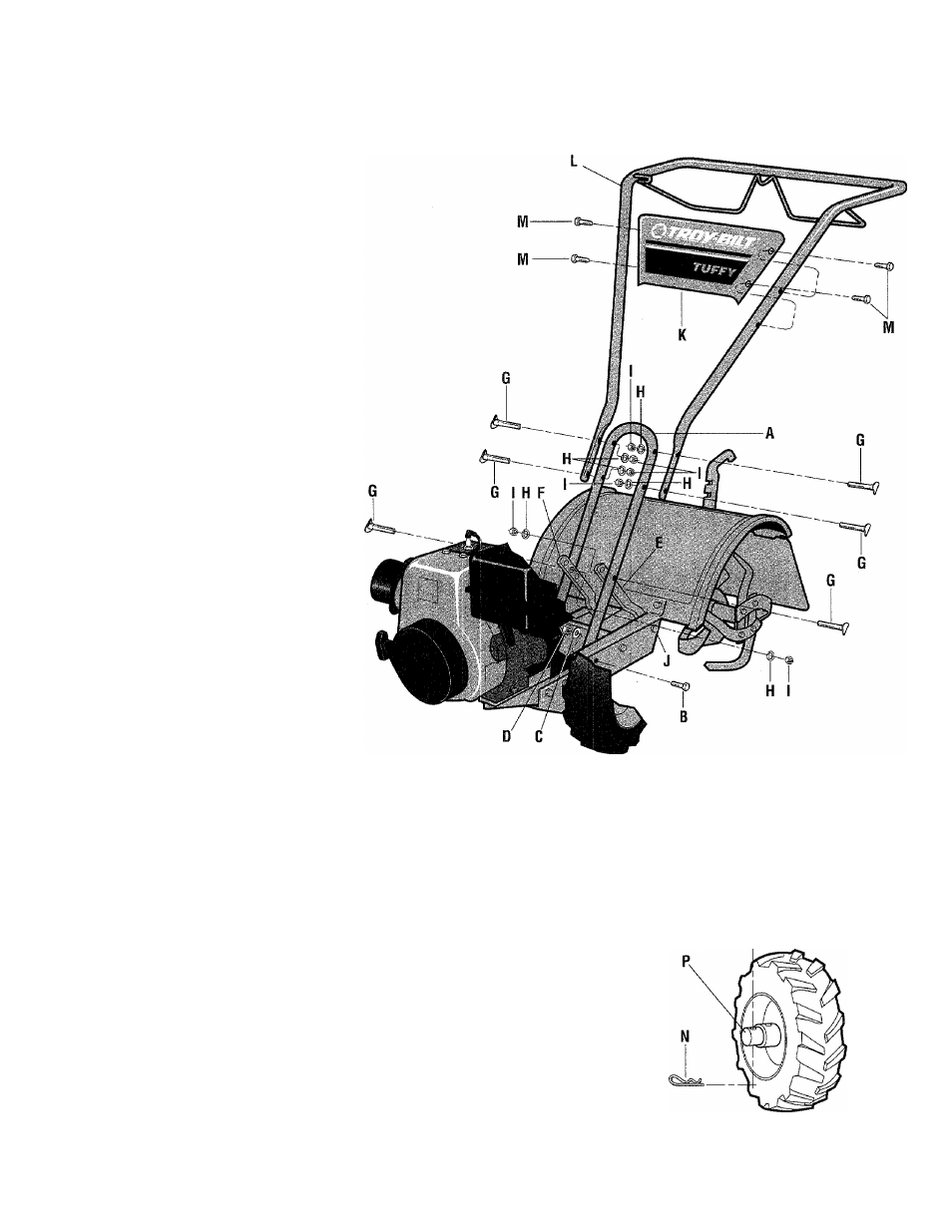
3. Attach the Handlebar
1.
Attach the legs of the handlebar
support (A, Fig. 2-2) loosely to the
inner sides of the tiller frame using
two 3/8"-16
X
3/4" hex hd. screws
(B), 3/8" flat washers (C) and 3/8"-
16 hex locknuts (D).
2.
Using the middle holes in the
handlebar support brackets (E and
F, Fig. 2-2), loosely attach the sup
port brackets to the handlebar sup
port (A) using two 5/16"-18 X 1-
1/2" curved hd. screws (G), 5/16"
split lockwashers (H) and 5/16"-
18 hex nuts (I). NOTE: If a sup
port bracket will not move, loosen
attaching screw (J) and nut.
3. Attach the handlebar panel (K,
Fig. 2-2) to the handlebar assem
bly (L) using four l/4"-20
X
1/2"
self-threading screws (M). Tighten
the four screws securely.
4.
Attach the handlebar assembly
(L) to the handlebar support (A)
using four 5/16"-18x 1-1/2"
curved hd. screws (G), 5/16" split
lockwashers (H) and 5/16"-18 hex
nuts (I). Tighten the four screws
securely.
5. Tighten all handlebar mounting
hardware securely.
Fig. 2-2: Assemble handlebar.
4. Move Tiller Off Shipping
Platform
To roll the tiller without the engine
running, the wheels must be
placed in their FREEWHEEL po
sition, as described below.
1.
Use a sturdy block to raise one
wheel off the ground.
2. Remove the hair pin cotter (N,
Fig. 2-3) and clevis pin (O). Slide
the wheel inward on the axle (P)
and reinstall the clevis pin and hair
pin cotter through the axle only
(not through the wheel hub).
Repeat with the other wheel.
3. Using the handlebar as a lever,
roll the tiller to a flat area.
IMPORTANT: Before starting
the tiller’s engine, the wheels must
be placed in their WHEEL DRIVE
position (pins through wheel hubs
and axle). This procedure is de
scribed in “Wheel Drive Pins” on
Pages 12-13 in Section 3.
Fig. 2-3: Wheel in FREEWHEELING
position.