Section, A warning, Tiller features and controls identification – Troy-Bilt 12065 User Manual
Page 12: A) wheel drive pins, Warning
Attention! The text in this document has been recognized automatically. To view the original document, you can use the "Original mode".
Section
Learn the locations of the tealiires
and controls on your machine
before starting the engine. Taking
the time now to understand the lo
cation. function and operation of
these controls v.'lll greatly add to
the productive use. safe operation,
and enjoyment of your machine.
For detailed step-by-step operating
instructions, please refer to
"Section ■ 1; Operation."
A WARNING
TO AVOID PERSONAL INJURY OR
DAMAGE TO EQUIPMENT:
Before using your tiller for the
first time, become thoioughiy fa
miliar with the operation of the
controls by moving them to their
various positions while the en
gine is not running. The proper
operation of each control is dis
cussed in detaii in Section 4.
NOTE:
All references to left, right,
front and rear of the machine are
determined by standing behind the
handlebars and facing the direction
of forv/ard travel.
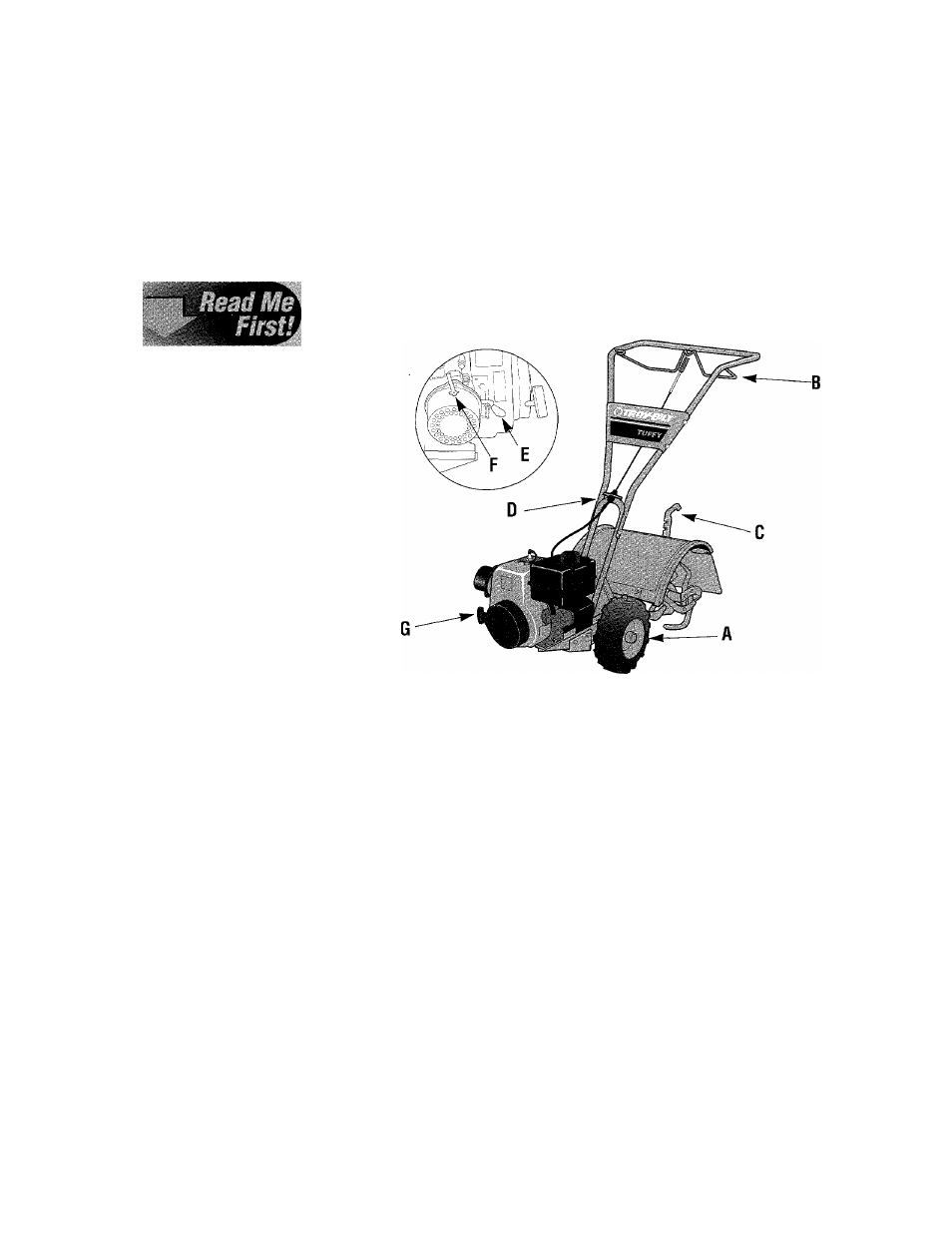
TILLER FEATURES AND CONTROLS IDENTIFICATION
The major tiller controls and features are identified and illustrated on the
next few pages. The use and operation of each control and feature is cov
ered in detail in Section 4 “Operating Instructions.”
Figure 3-1: A- Wheel Drive Pins; B- Forward dutch Baii; C- Depth
Regulator Lever; D- Handlebar Height Adjustment; E- Engine Throttie
Lever; F- Engine Choke Lever; G- Engine Recoii Starter.
A) Wheel Drive Pins
These two pins (one on each
side of the wheel shaft), secure the
wheels to the wheel shaft and can
be positioned by you to put the
wheels in either a WHEEL DRIVE
or a FREEWHEEL mode.
Before starting the engine, put
both wheels in the WHEEL
DRIVE position by inserting the
Wheel Drive Pins through the
holes in
both
the wheel shaft and
wheel hub on both sides of the
tiller. This “locks” the wheels to
the wheel shaft, causing the wheels
to turn when you engage the
Forward Clutch Bail.
Use the FREEWHEEL position
only when the engine is off. This
A
WARNING
Never let either of the wheels
be in FREEWHEEL position
when the engine is running.
Always put both wheels in the
WHEEL DRIVE position before
starting the engine.
Failure to comply could cause
loss of tiller control, property
damage, or personal injury.
position lets you easily push or
pull the tiller. To use FREE
WHEEL, place the Wheel Drive
Pins only through the holes in the
wheel shaft. This keeps the wheels
on the shaft, but allows the wheels
to rotate when you push or pull the
tiller handlebar.
12