Warning, Bolo tines, Removing and installing tine assemblies – Troy-Bilt 12065 User Manual
Page 27: Removing and installing individual tines
Attention! The text in this document has been recognized automatically. To view the original document, you can use the "Original mode".
Tightening Tiiier Hardware
A
WARNING
Stop the engine, allow it to
cool, disconnect the spark
plug wire and prevent it from
touching the spark plug be
fore tightening any bolts,
screws, or nuts.
Failure to do so could result
in personal injury or property
damage.
After the first two hours of tiller
operation, check all fasteners (nuts,
bolts, screws, pins, etc.) and
tighten any that may have loosened.
After this initial check, check those
same fasteners after every ten
hours of tiller operation.
Most of the fasteners on your
tiller are in plain view. However,
the following ones are not readily
visible. Be sure to check them for
tightness as well.
1. Rear End Cap Bolts- These
three bolts are located at the rear
end of the tiller transmission. Lift
up the hood flap to view them.
2. Transmission Housing Cover
Bolts- These four bolts are lo
cated on the top of the rear end of
the tiller’s transmission. You see
them when you lift the hood flap.
Bolo Tines
As you use your tiller, the tines
will gradually wear. They will be
come shorter, narrower and
pointed, decreasing their ability to
till effectively. Check the tines for
wear several times a season, and
replace badly worn tines to restore
your tiller's effectiveness.
Removing and Installing
Tine Assemblies
A
WARNING
stop the engine, allow it to
cool, disconnect the spark
plug wire and prevent it from
touching the spark plug be
fore removing or installing a
tine assembly.
Failure to comply could result
in personal injury or property
damage.
1. Use a 9/16" socket, 6” exten
sion, a ratchet, and a 9/16" box end
wrench to loosen the nut and bolt
that secure the tine holder to the
tine shaft. See Photo 5-11.
Photo 5-11: Removing tine assembly.
2. Use a rubber mallet to tap the
tine holder loose.
3. Slide the tine assembly off the
tine shaft.
4. Repeat Steps 1 -through-3 above
to remove the other tine assembly.
5. Installing the tine assembly is
simply the reverse of its removal.
First be sure to remove any rust,
uneven spots or burrs from the tine
shaft, using fine sandpaper. Then
grease the tine shaft before rein
stalling the tine assemblies. Tight
en the hardware very securely.
Removing and Installing
Individual Tines
1. Use two 9/16" box end wrenches
to remove the two bolts, nuts and
WARNING
stop the engine, allow it to
cool, disconnect the spark
plug wire and prevent it from
touching the spark plug be
fore removing or installing
tiller tines.
Failure to comply could result
in personal injury or property
damage.
lockwashers that secure the tine to
its tine holder. See Photo 5-12.
NOTE: If the nuts are rusted,
apply penetrating oil to the bolt
and nut. Let the oil soak in for
several minutes before loosening
the nut. Always loosen the nut
rather than the bolt.
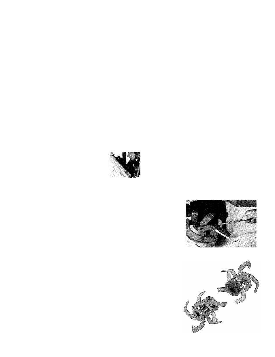
3. When installing individual
tines, install them in the reverse
order from which they were re
moved. All tine tips must point in
ward toward the transmission.
Also be sure the cutting edges face
so they will enter the soil first
when the tiller is moving forward.
Photo 5-12: Removing one tine.
Figure 5-13: Install tines as above.
21