Ariens Sno-Thros 924000 Series User Manual
Page 7
Attention! The text in this document has been recognized automatically. To view the original document, you can use the "Original mode".
2. Roll the attachment belt on to the engine sheave. Pull the
recoil starter rope to turn the engine sheave and roll the belt
into place under the belt finger.
3. Check the belt finger spacing. There should be 1/8 inch
clearance all around the belt finger and belt with the
attachment clutch engaged. Readjust the belt finger if
required.
4.
Check the sheave alignment with the attachment belt in
place. Readjust the position of the blower sheave as re
quired to align the sheaves. Be sure the brake pad aligns
with the blower sheave.
5. The idler on the attachment belt is adjustable. If the belt
slips, adjust the idler in the slot in the idler arm to apply
more tension to the belt. Belt should declutch when
attachment clutch is disengaged.
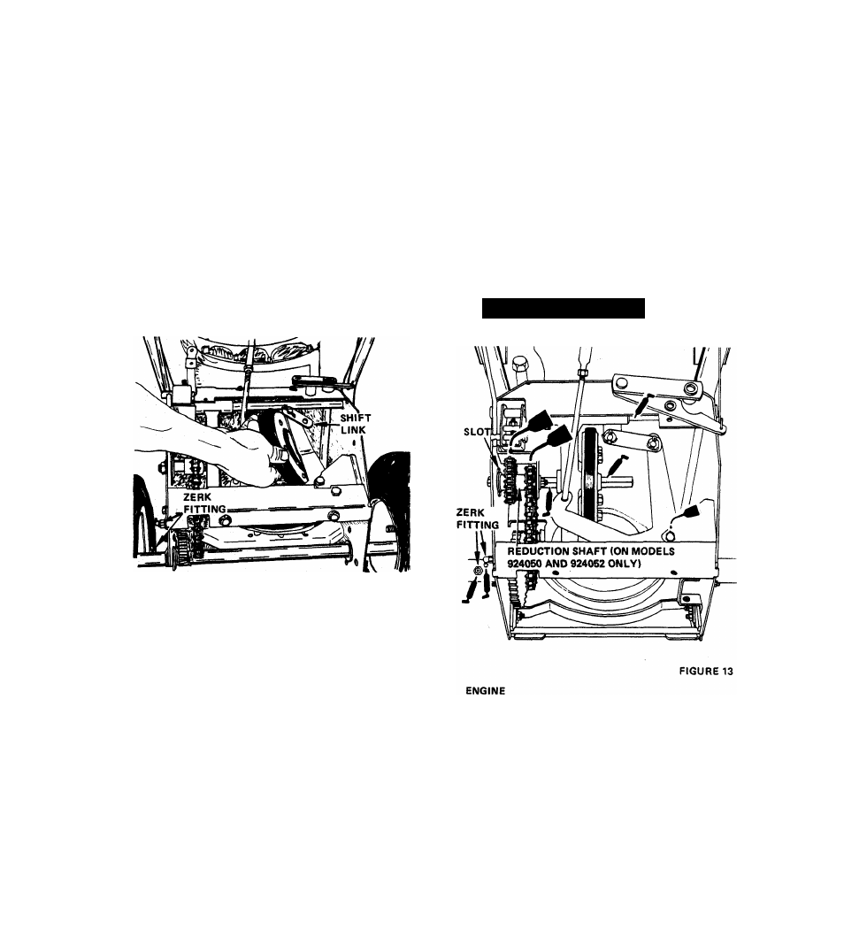
DRIVE CHAIN ADJUSTMENT
MODELS 924050 and 924052
If sno-thro is difficult to push because of tight or inter
fering drive chains, proceed as follows:
1. Stand unit up on blower housing and remove bottom cover.
2. Chain tension is adjusted by loosening the two nuts on
the 24364 Reduction Shaft. Adjust reduction sprocket
up or down in slot to obtain proper tension (chain should
be snug). Retighten both nuts. Torque to 170-180 inch
lbs.
3. Chain interference with the 3085 Bearing Flange on 24045
Hex Shaft occurs if these is no 64058 Washer between the
10276 Sprocket and 54079 Bearing. Install washer.
6.
Replace the belt guard and chute crank assemblies.. Re
adjust the chute crank as described in the paragraph above.
Replace the spark plug wire.
L U B R I C A T I O N
FIGURE 12
REPLACEMENT OF FRICTION WHEEL
1. Tip the machine up on the blower housing and brace
securely. Remove two cap screws and loosen the other two,
securing the bottom cover and remove the cover.
2. Place the speed selector in FIRST position. Depress the
wheel drive clutch lever to hold the friction wheel while
the five bolts securing the friction wheel to the hub are
loosened. Remove the five bolts, shift to THIRD position
and disconnect the shift link. See Figure 12.
3. Position a new friction wheel on the hub and replace the
five bolts. Tighten these bolts to 8-10 foot pounds with
a torque wrench. Replace the shift links.
4.
Replace the bottom cover. Readjust the drive disc as
described in the WHEEL DRIVE CLUTCH ADJUSTMENT
on page 5.
Fill
crankcase
with
Ariens
Sno-Thro
oil
5W-20
when
using Sno-Thro at temperatures below 40 degrees F.
Use Ariens Gard-N-Yard oil MS classification SAE-30 when
using lawn attachments at temperatures above 40 degrees F.
Fill fuel tank with fresh, clean, regular gasoline.
NOTE:
For detailed instructions on engine refer to manufacturer's
booklet packed with the machine.
- 7 -