Ariens Sno-Thros 924000 Series User Manual
Page 6
Attention! The text in this document has been recognized automatically. To view the original document, you can use the "Original mode".
CHUTE CRANK ADJUSTMENT
In the event the chute crank fails to rotate freely, loosen the
nut securing the worm clevis to the bracket. This hole in the
bracket is slotted to permit adjustment. Position the worm
so there is a little clearance between worm and the gear
teeth on the blower. Tighten the nut. Rotate the discharge
chute through its full travel to see that it turns easily. Re
adjust if required. Uubricate as described under LUBRICATION
for smooth operation.
BELT REPLACEMENT
A
CAUTION
Since replacing the belts will involve turning the engine over
with the starter, and the engine might accidentaily start, re
sulting in injury, the spark plug wire MUST be disconnected
during this procedure.
The drive belt and the attachment drive belt are both accessible
by removing the blower housing as follows;
1. Remove the hair pin cotter in the chute crarik assembly.
Separate the chute crank.
2. Remove the two flanged whizlock screws securing the belt
guard to the tractor. Remove the belt guard.
NOTE:
Tipping
the
tractor
back
on
the
handlebars
when
separating the units may result in bending the bottom cover.
To avoid diis situation, either tip the unit up on the blower
housing and remove the bottom cover before separating the
units; or support the handlebars so the tractor does not tip all
the way over; then lift off the blower housing.
3. Remove the cap screws on each side that secures the blower
housing to the frame. As the blower housing and tractor
are tipped apart, roll the belt off the engine sheave between
the sheave and belt finger. This can be easily done by
pulling the recoii starter rope to rotate the engine sheave.
With the beit disconnected, the biower housing may then
be lifted from the frame.
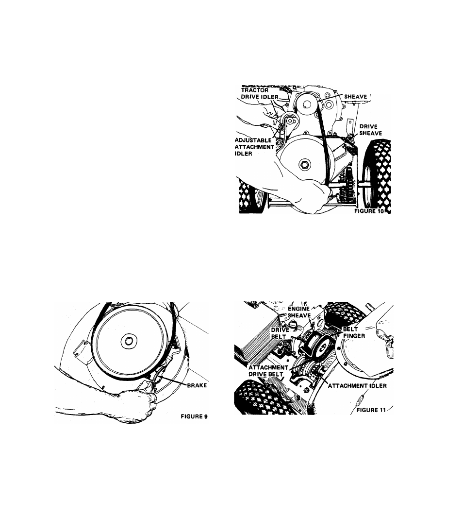
REPLACEMENT OF THE ATTACHMENT DRIVE BELT
The sno-thro attachment drive belt is on the sheave on the
blower housing. To replace this belt, hold the impeller brake
away from the belt and slip the belt from the sheave. See
Figure 9.
Replace the belt by slipping it into position on the sheave;
positioning the brake shoe on the belt.
REPLACEMENT OF TRACTOR DRIVE BELT (See Figure 10.)
The drive belt is held in place on the sheaves by an idler
pulley. To free the belt, the idler can be pulled from the
belt and the belt removed from the sheave. Activate clutch to
gain clearance. It may be necessary to pull back blower idler
arm clevis pin for additional clearance.
ENGINE
To replace the belts, position on the engine sheave first,
then on the drive sheave. .Position the idler carefully on the
belt.
With the belt in position and the idler in place, check the
belt alignment. The engine sheave and the tractor sheave must
align
with
one
another
WITH
THE
TRACTOR
CLUTCH
ENGAGED. If the sheaves are not properly aligned, loosen the
setscrews on the engine sheave and align the sheaves. Re-tighten
the setscrews. Recheck the belt alignment WITH THE CLUTCH
ENGAGED.
REPLACEMENT OF BLOWER HOUSING (See Figure 11.)
Position the blower housing on the rod in the tractor frame
and secure as follows:
1.
Tip the blower and tractor together. Hold the attachment
drive belt up as the units are tipped together. Secure with
two cap screws into the frame. As the cap screws are
tightened, hold up on the handlebars to be sure the two
units are secured together.
- 6