Ariens Sno-Thros 924000 Series User Manual
Page 5
Attention! The text in this document has been recognized automatically. To view the original document, you can use the "Original mode".
TO TRANSPORT:
Move speed selector to desired speed.
Press down on handle bars to raise front of Sno-Thro
slightly off the ground.
Depress wheel drive clutch lever to transport unit.
TO OPERATE:
Move deflector to desirwJ height.
Turn hand crank
direct discharge chute.
Depress attachment clutch (£) to engaged position.
Move speed selector to desired speed.
Move throttle (T) to desired speed.
Depress the wheel drive clutch lever to move tractor.
Speed of the machine is controlled by the throttle and
speed selector.
TOSTOP:
Release wheel drive clutch lever Qj Depress attachment
clutch lever ^ to allow the Sno-Thro to run for a short
time to throw out slush and water and prevent freezing the
impeller fan.
Turn key(^ to "off" position to stop.
5 and 7 HP Models: Move throttle to "FAST" position after
engine has stopped.
8 and 10 HP Models: Move throttle to "SLOW" position
after engine has stopped.
NOTE: This Sno-Thro is equipped with a mechanics/ inter-
iock between wheel drive dutch and attachment dutch levers.
When both dutch levers are engaged the mechanical interlock
mil engage and the attachment dutch will remain angled as
long as the wheel drive dutch lever is not released. This frees
the right hand to operate other controls. Once the mechanics/
interlock
is
engaged,
both the wheel drive
and attachment
clutch levers must be released to disengage the attachment
drive.
Ariens Company recommencte that you have adjustments
made by your local Ariens dealer. He has the tools and know
how to properly perform these maintenance adjustments
which may be required to Heap the Sno-Thro operating at
peak efficiency. The Sno-Thro is equipped with the finest
quality engine obtainable. However, should servicing be
required, it can be obtained from an Ariens dealer or an
authorized engine manufacturer's service station. Should you
decide to make adjustments on your Sno-Thro yourself,
Ariens recommends that you call your dealer for the answers
to any questions that might arise in performing this work.
SHEAR BOLT REPLACEMENT
—_
Occasionally a small object may enter the collector and jam
the rakes. When this occurs, the shear bolts securing the rakes
to the shaft will break and allow the rake to turn freely on the
shaft preventing damage to the gear drive. When this happens,
turn off the engine, remove wire from spark plug, remove the
broken shear bolt and replace with a new ARIENS shear bolt.
Use of any other type of shear bolt may result in severe
damage to the machine. USE ONLY ARIENS SHEAR BOLTS
FOR REPLACEMENT.
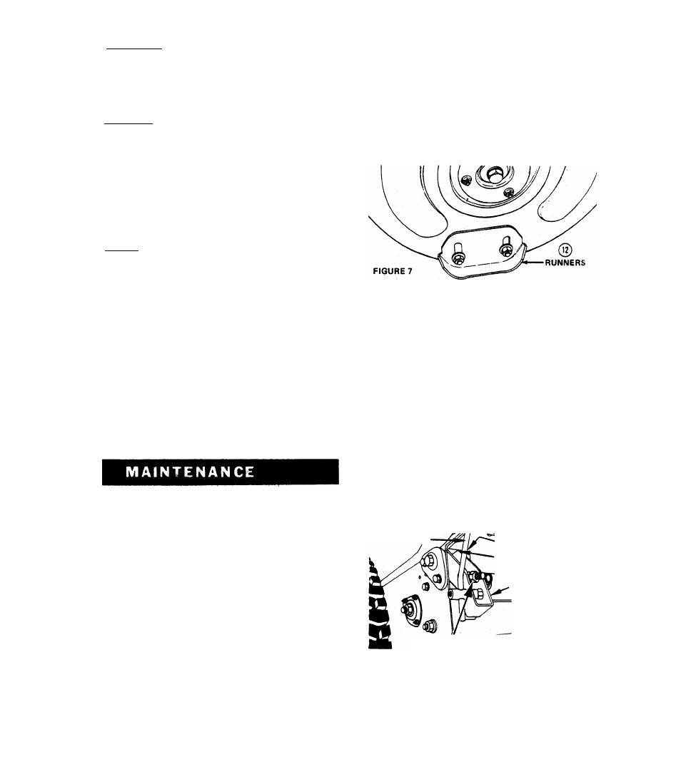
RUNNERS AND SCRAPER BLADE
The runners on each side of the blower housing, and the
scraper blade, along the back of the blower housing, are all ad
justable to suit conditions. Raising or lowering the runners
controls the distance the scraper blade is held above the sur
face being cleared. Runners are adjusted by loosening the two
nuts securing each runner. Move the runner to the desired
position and retighten the nuts. Be sure to adjust both runners
to the same height to keep blower housing level. Uneven
runners make the machine difficult to steer and will result in
an uneven clearing job.
Adjustment of the runners is critical to good cleaning. If the
machine is to be used on a gravel surface lower the runners
so the. blower will not pick up gravel then after the remaining
snow is packed down, the runners may be raised for close
scraping. On smooth concrete or blacktopped surfaces, the
runners may be raised so the scraper blade rests on the sur
face and scrapes clean.
The scraper is adjustable so it may be lowered to compensate
for wear. If the blade is allowed to wear down too far the
blower housing may be damaged.
ATTACHMENT CLUTCH ADJUSTMENT
The Attachment Clutch is adjusted by connecting the chain
to the spring just below the clutch handle. Connect the spnnii
to a chain link so the chain is snug but so the idler drops away
from the belt with the handle all ^e way up.
WHEEL DRIVE CLUTCH ADJUSTMENT
A drive disc adjustment is provided to compensate for wear
on the friction wheel. If slippage occurs when the wheel
drive clutch it engaged, tighten the drive disc adjustment. This
adjustment is accessibie without removing the bottom cover.
See Figure 8.
CLUTCH ROD
TOP OF SLOT
1/16" CLEARANCE
CLUTCH LEVER
ADJUSTMENT NUT
FIGURE 8
Adjust as follows: Place speed selector between first and
reverse. Tip machine forward on blower housing. Tighten
the adjustment nut while turning the wheels until the wheels
begin to bind. Back off 3 turns. Wheels should then turn
easily.