Deflector, Chute crank, Tire pressure – Ariens Sno-Thros 924000 Series User Manual
Page 16: Mechanical interlock, Runners- on model 924052 only, Belt adjustment, Engine, Drive chain adjustment, Long bolt runner
Attention! The text in this document has been recognized automatically. To view the original document, you can use the "Original mode".
8. DISCHARGE CHUTE (MODEL 9240S2 ONLY)
13. BLOWER GEAR CASE
The discharge chute is shipped with the four mounting clips
attached to the chute. Remove the clips and hardware. Po
sition the discharge chute on the blower housing. Secure with
the clips and hardware. Be sure the chute rotates freely.
On 32" Models 924052, and 824008. Check the oil level in the
auger gear case. Oil level must be even with the oil filler hole.
Fill with Ariens Special L-2 Gear Lubricant. Replace the filler
plug.
9. DEFLECTOR
The deflector is installed on the discharge chute but must be
raised into operating position. Remove the carriage bolt and
wing nut. Rotate delfector up into operating position. Reinstall
the carriage bolt and wing nut.
On 24" Models 924046, 924048, 924050, 824006 and 824007.
The blower gear case if factory lubricated and should require
no lubrication by the dealer. Full instructions for checking are
given in the LUBRICATION section of the manual.
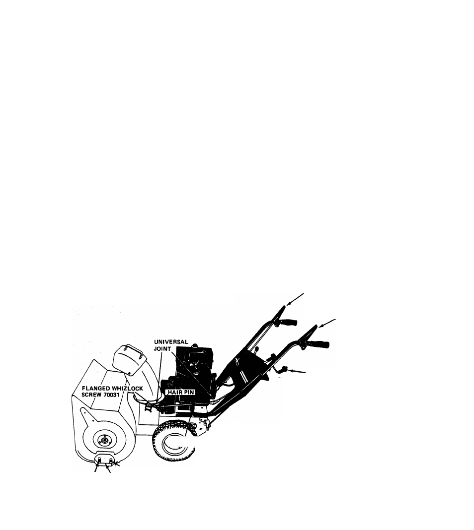
10. CHUTE CRANK
14.TIRE PRESSURE
The chute crank is packed separately in the carton. The inter
mediate shaft, universal joints and chute crank bracket are in
place on the machine. The chute crank bracket should be in
stalled on the rear, left hand stud at the time the handlebars
are installed. Insert the chute crank down into the hole in the
handlebar panel and connect to the universal joint on the
intermediate shaft with the hairpin cotter provided. On all
models, after completing the chute crank connection, check
the alignment of worm and chute by rotating the discahrge
chute through its full travel. Chute should rotate easily, if
not, reposition worm as required.
Tires have been over inflated for shipping purposes. For
operation, reduce tire pressure to 12 to 20 PSI. If tire chains
are used, a pressure of 20 PSI is recommended for proper
operation.
15.MECHANICAL INTERLOCK
Check for proper operation of mechanical interlock. Adjust
slider hardware if necessary to assure free operation. See page
5 for proper operation of mechanical interlock.
11. RUNNERS- ON MODEL 924052 ONLY
Install runners on each side of the blower housing. Use
longer carriage bolts (62013) in the rear holes, shorten
carriage bolts (6201.0) in the front holes. Use a washer
(64002) and locknut (65039) on each bolt outside thé
housing. Adjust the runners to equal height on each side. See
paragraph on page 5 for proper adjustment.
16.
BELT ADJUSTMENT
Check the position of the belt fingers on the engine sheave
and the alignment of the sheaves. Adjust as shown in Figure
10 and as described in REPLACEMENT OF TRACTOR
DRIVE BELT on page 6.
12.
ENGINE
Before starting the engine, fill the crankcase with Ariens Sno-
17.
DRIVE CHAIN ADJUSTMENT
If Models 924050 or 924052 Sno-Thro are difficult to push
because of tight or interferring drive chains, re-adjust as des
cribed in DRIVE CHAIN ADJUSTMENT on Page 7.
Thro oil 5W-20 for snow blower operation below 40 degrees
F. Use Ariens Gard-N-Yard oil 10W-30 for operation at
temperatures above 40 degrees F.
ATTACHMENT CLUTCH
TRACTOR CLUTCH
CHUTE CONTROL CRANK
•(■CHUTE CRANK BRACKET
^ yi I
DEALER
MUST
MAKE
SURE
ALL
SAFETY
DEVICES
AND
GUARDS
ARE
IN
POSITION
AND
OPERATING
PROPERLY.
DEALER
MUST
INSTRUCT
THE
CUSTOMER
ON
SAFETY
PRECAUTIONS,
OPERATION,
CARE
AND
MAINTENANCE.
FILL
OUT
WARRANTY
REGISTRA
TION AND MAIL TO ARIENS COMPANY.
SHORT BOLT
LONG BOLT
RUNNER
FIGURE 18
- 1 7 -