Dealer up and pre-service – Ariens Sno-Thros 924000 Series User Manual
Page 15
Attention! The text in this document has been recognized automatically. To view the original document, you can use the "Original mode".
DEALER
UP AND PRE-SERVICE
1. GENERAL
All hardware and parts required for assembly are shipped in
the parts bag pr are located, in place, on the machine. The
upper handlebars and panel are assembled at the factory with
the two clutch rods and interlock system in place and adjusted.
The lower handlebars must be installed. The snow head and
tractor are shipped assembled with lower shift rod in place.
Attachment clutch rod is in place on handle panel assembly.
Model 924052 (the 32" snow head) is shipped with the runners
and discharge chute detached and they will have to be
installed.
2. HANDLEBAR
Install the lower handlebars on the frame using the studs and
hardware in place on the frame. (Leave the hardware loose on
the studs until the upper handlebars are installed). Be sure to
install the chute crank bracket on the left rear stud on top of
the handlebar.
Install the upper handlebar and panel on the lower handlebars.
Use a flat washer on the outside of each cap screw. Use a 5/8"
carriage bolt and locknut in each of the top holes, and an
VA" carriage bolt and locknut in each of the lower holes. With
everything in place, tighten all handlebar hardware.
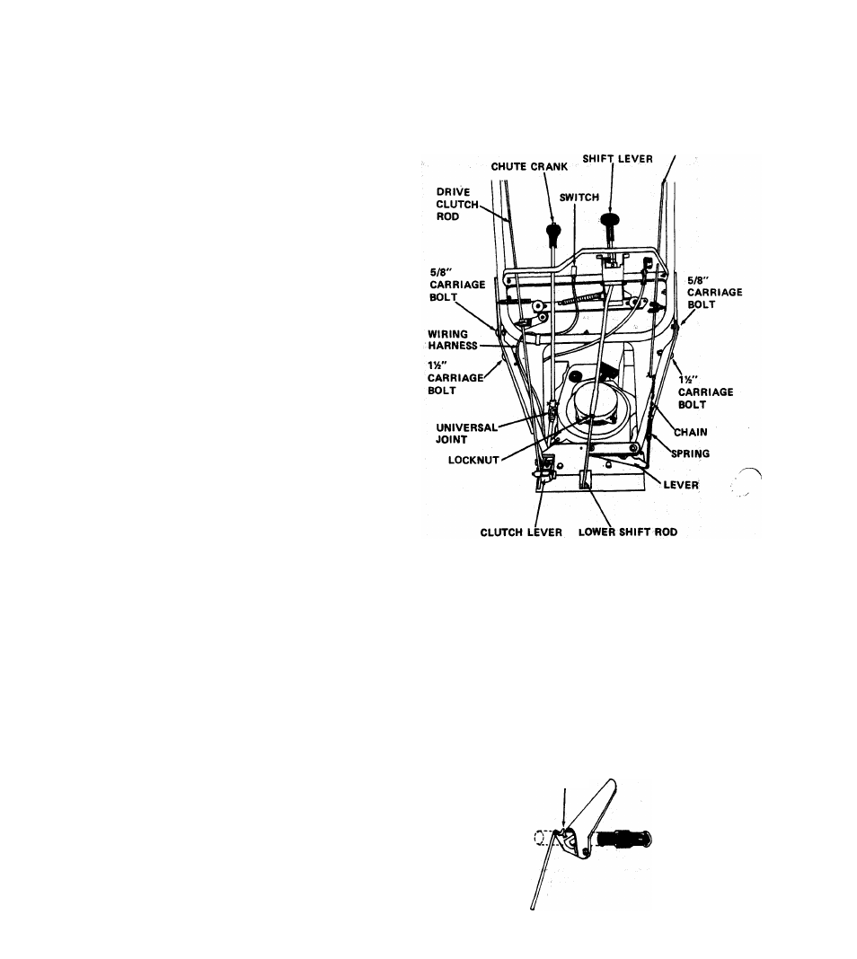
3. THROTTLE CONTROL
Route throttle control under handlebar and insert into
position in handlebar panel. See Figure 16. Secure with
two machine screws #(10-24xVa) and two keps nuts
from parts bag. Install knob on throttle lever.
4. SHI FT CONTROL ROD
Remove the upper shift rod from the shift lever and place the
shift lever in REVERSE position. Pull up on the lower shift
rod which is already installed in the frame. Hold the lower
shift rod up while screwing the upper rod in place. Turn the
upper rod into the lower until the end of the upper rod
lines up with the hole in the shift handle. Install the upper rod
in the shift handle and tighten the locknut joining the upper
and lower shift rods.
S. ATTACHMENT CLUTCH ROD
The attachment clutch rod is installed in the upper handlebars
but the chain must be hooked to the spring already in place on
the clutch bell crank. Connect the spring to a link in the chain
that will keep the chain snug without pulling up on the bell
crank. The clutch idler pulley must tighten up on the belt
when the handle is down and must fall away from the belt
when the handle is upright. Adjust chain as required.
6. DRIVE WHEEL CLUTCH ADJUSTMENT
a. The clutch handle is already positioned on the handle
bar and the tractor clutch rod is in place in the handle.
Check to be sure the clutch handle is free to fall down
on the grip.
b. Insert the lower end of the tractor clutch rod into the
rod adapter.
ATTACHMENT
CLUTCH ROD
FIGURE 16
c. Position the clutch handle so that it is all the way up.
See Figure 17.Tighten the tractor clutch rod in the rod
adapter with the setscrew. With handle down, clutch
lever should come within 1/16" of top of slot in frame.
Adjust as required. See Figure 8 of owners section.
7. KEY SWITCH CONNECTION
The key switch is factory installed in the handlebar
panel and the wiring is connected to the engine. Route
the wiring harness up the inside of the panel, alongside
the lower handlebar. Connect wire harness to switch.
See Figure 16.
TIP HANDLE FORWARD
AS FAR AS POSSIBLE
FIGURE 17
-16