Gear drive belt path (top view), Hydro drive belt path (top view), Drive belt removal/lnstallation – Troy-Bilt 13034 User Manual
Page 30: Tire pressure, Do not over-inflate tires, Hood removal/lnstallation, Maintenance (continued)
Attention! The text in this document has been recognized automatically. To view the original document, you can use the "Original mode".
Maintenance (continued)
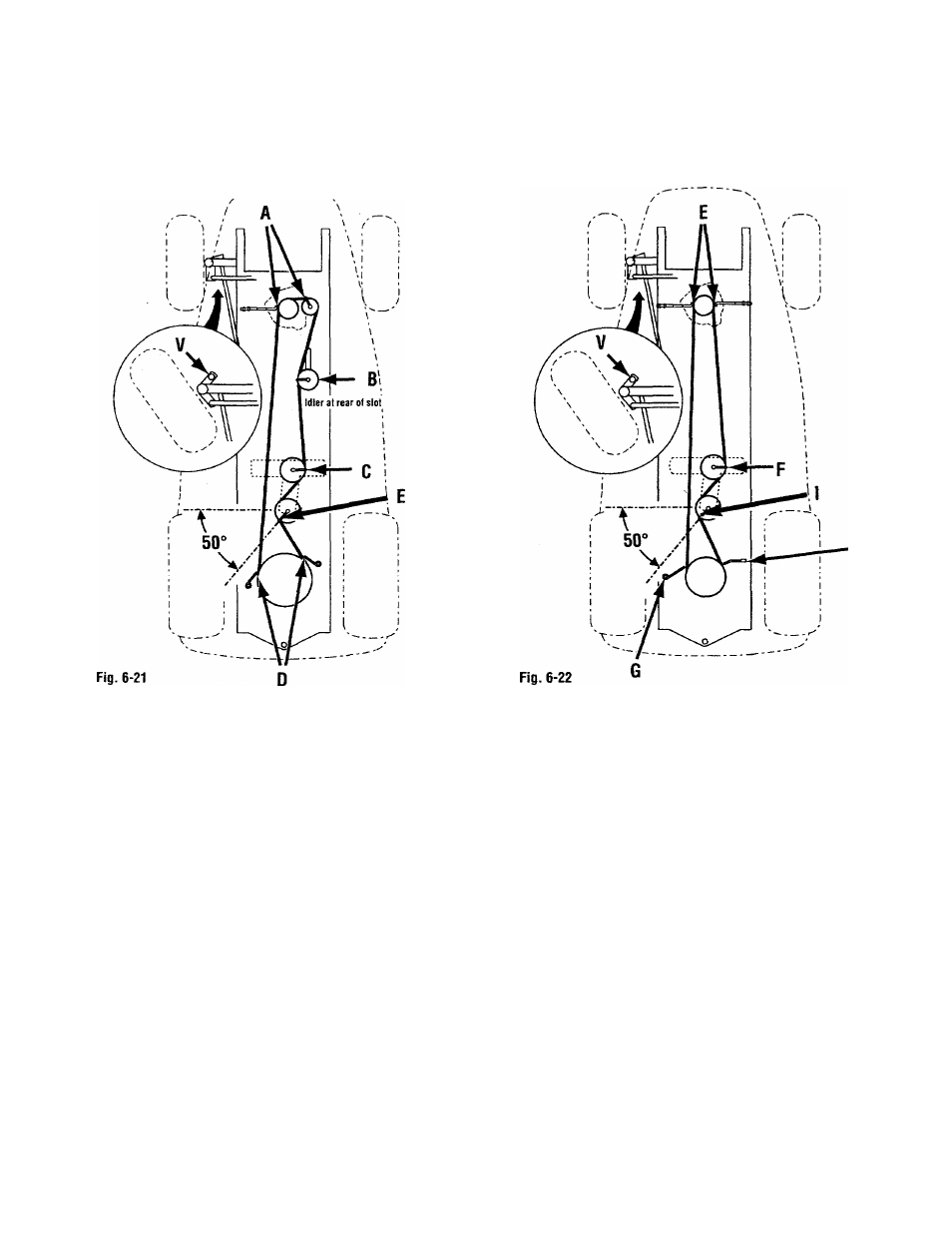
Gear Drive Belt Path
(TOP VIEW)
Hydro Drive Belt Path
(TOP VIEW)
H
Drive Belt Removal/lnstallation
Set parking brake. Place drive controls
into neutral position before
removing/installing belts. Removing
fender will aid belt replacement/
adjustment (see “Fender Removal” earlier
in this section).
DRIVE BELT REMOVAL:
• Turn steering wheel to the LEFT. Remove
locknut (V, 6-21 & 6-22) at drag link. Do
not rotate balljoints.
• Loosen all belt guides and work belt
from belt path and off unit.
DRIVE BELT INSTALLATION;
GEAR DRIVE UNITS:
•
Route belt around sheaves as shown in
Fig. 6-21.
•
• Adjust belt guides (A, Fig. 6-21) 1/16” to
1/8” away from belt. Secure guides (A).
30
• Adjust belt guide (B) so it is pointing
straight to the left of the unit as shown in
Fig. 6-21. Secure guide (B). NOTE: Adjust
Idler all the way to the rear In slot.
•
Adjust belt guide (C) so it is pointing
straight to the right of the unit as shown in
Fig. 6-21. Secure guide (C).
• Adjust belt guides (D) 1/16" to 1/8” away
from belt. Secure guides (D).
• Adjust belt guide (E) so it is pointing 50°
back from straight left, as shown in Fig. 6-
21. Secure guide (E).
HYDROSTATIC DRIVE UNITS:
• Route belt around sheaves as shown in
Fig. 6-22.
•Adjust belt guides (E) 1/16” to 1/8” away
from belt. Secure guides (E).
• Adjust belt guide (F) so it is pointing
straight to the right of the unit as shown in
Fig. 6-22. Secure guide (F).
•Adjust belt guides (G and H) 1/16” to
1/8” away from belt. Secure guides (G
and H).
•Adjust belt guide (I) so it is pointing 50°
back from straight left, as shown in Fig. 6-
22. Secure guide (I).
• Re-install fender if necessary.
Tire pressure
Always maintain proper tire pressure.
a. Front—12 -14 PSI (82 - 96 kPa)
b. Rear—8 -10 PSI (55 - 69 kPa)
NOTE: Inflate both front tires evenly.
Inflate both rear tires evenly. Unit will
not be level if this instruction is not
followed.
DO NOT OVER-INFLATE TIRES!