Steering check, Cruise control [optional—standard on model 13037, Attachments – Troy-Bilt 13034 User Manual
Page 20: Attachment/pto drive, Ahachment lift, Ground contour method, Frame hung method, Attachment lift, Operation (continued)
Attention! The text in this document has been recognized automatically. To view the original document, you can use the "Original mode".
Operation (continued)
Steering Check
Drive unit slowly while turning steering
wheel. Check for binding, sloppy or
restricted movement. Stop unit and
service any problems before continuing.
Cruise Control [optional—standard on
model 13037]
Cruise control can only be used on
hydrostatic drive units. Cruise control
allows the operator to maintain a constant
drive speed without contacting the travel
pedal. When activated, cruise control sets
travel pedal at the desired position.
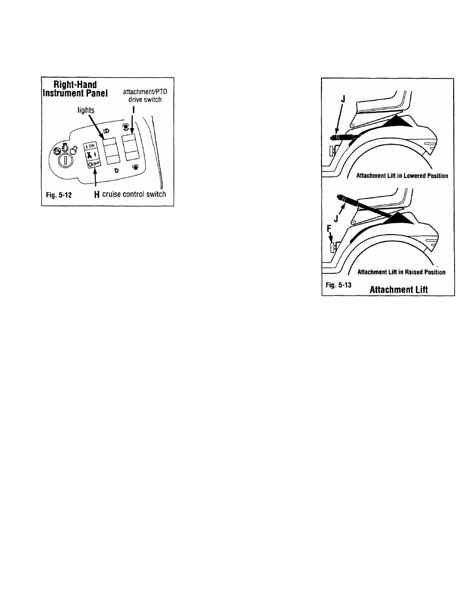
TO SET: Press switch to “ON” (H, Fig. 5-
12) to activate speed control.
TO STOP: Press brake pedal or turn
cruise control switch off.
Attachments
Attachments for this unit are supplied with
literature containing important safety,
operation and maintenance information.
Read and understand all literature
provided with any attachments to be used
with this unit before use.
Attachment/PTO Drive
ELECTRIC CLUTCH BREAK-IN
PROCEDURE
Note: Perform this step with mower deck
or snowthrower attachment mounted on
unit.
With engine running at full throttle,
engage and disengage attachment/PTO
drive switch 10 to 15 times. Engage
attachment drive at 3/4 throttle, during
break-in. Perform this step before initial
use and after extended storage. See
Section 2, “Attachments & Kits” on page 9
for specific attachment and kit
descriptions.
Attachment/PTO drive is controlled by
attachment/PTO drive switch (I, Fig. 5-12).
AHACHMENT LIFT
Before using attachment lift, make sure
the attachment is completely and properly
secured. Read all literature provided with
attachments to be used with this unit.
It is possible to customize tractor lift
mechanism to operator and terrain. To
adjust spring tension, tighten or loosen
screw (X, Fig. 5-11).
Note: incorrect tift spring adjustment
may require a iarge amount of force to
operate fifí. Correct adjustment witi
etiminate this probiem (Modeis 13034 &
13035 are not equipped with tift spring.
A iitt assist kit, part
# 1767979, is
avaiiabie for these units).
Cutting
methods are described below.
Ground Contour Method
This method allows attachment to follow
ground contours. This is the
recommended method used when
operating attachments such as
snowthrowers, tillers, etc. See
owner/operator manual provided with your
attachment for more information.
Frame Hung Method
“Frame hung cutting” is recommended
when cutting over smooth terrain. This
method allows the mower deck to hang
from tractor frame If deck contacts a
bump, front anti-scalp wheels and rear
gage wheels contact ground and lift deck
to avoid scalping.
Note: Height adjustment knob (F, Fig 5-
13) must be turned to the fuii-down
position when ground contour cutting.
20