A warning, Spark plugs, Fuse – Troy-Bilt 13034 User Manual
Page 26: Fender removal, Maintenance (continued)
Attention! The text in this document has been recognized automatically. To view the original document, you can use the "Original mode".
Maintenance (continued)
A WARNING
BAHERIES GIVE OFF HIGHLY
EXPLOSIVE GAS DURING AND FOR SOME
TIME AFTER CHARGING. DO NOT ALLOW
A SPARK OR OPEN FLAME NEAR
BAHERY. USE A FLASHLIGHT TO
CHECK ELECTROLYTE LEVEL.
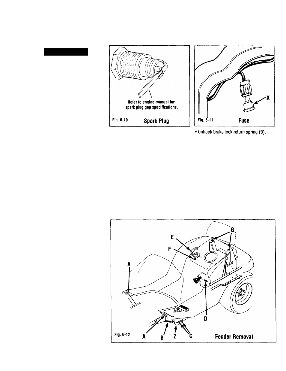
Spark Plugs
Every 100 hours, remove plugs and check
condition. Reset gap to specifications
indicated in engine manual. Do not
service a plug in poor condition. Best
results are obtained with a new plug. See
Figure 6-10. See the engine manual
provided with your unit to determine
proper replacement plug. USE OF
INCORRECT PLUG CAN DAMAGE ENGINE.
Under good operating conditions, the plug
will have a light gray coating or a tan
deposit. A dull white, blistered coating
could indicate overheating. A black
(carbon) coating could indicate an over
rich fuel mixture caused by a clogged air
cleaner or improper carburetor
adjustment.
NOTE: Do not clean spark plugs in
machines which use abrasive grit.
Clean spark plugs by scraping or wire
brushing or washing with a commercial
solvent.
Fuse
There is one (use (X, Fig. 6-11) located
under hood in wiring harness behind
instrument panel. Replace as necessary
with standard 20-amp, automotive-type
fuse.
NOTE: A blown fuse is a symptom of an
electrical problem. Simply replacing
fuse DOES NOT correct such a problem.
Fender Removal
Fender removal is simple and provides
excellent access to drive and lift systems.
It is not necessary to remove fender to
perform basic maintenance. NOTE: Lifting
tender from unit requires two people.
•
GEAR DRIVE UNITS; Unscrew and
remove gear shift knob from shift lever.
• ALL UNITS: Place lift lever into UP
position.
• Remove bolts and nuts retaining two
front edges of fender to frame (A, Fig. 6-
12
).
• Remove bolts and nuts (C) securing
brake pedal assembly to brake arm.
Remove brake pedal assembly.
• Reach under fender and remove hair pin
(D) securing lift height adjusting knob.
Remove knob.
• Loosen hand knobs under seat and move
seat back. Re-tighten hand knobs.
• Disconnect seat switch lead (E) from
seat switch. Push lead and rubber
grommet (F) down through fender.
26