Gear shift rod adjustment, Caution – MTD 214-412-000 User Manual
Page 8
Attention! The text in this document has been recognized automatically. To view the original document, you can use the "Original mode".
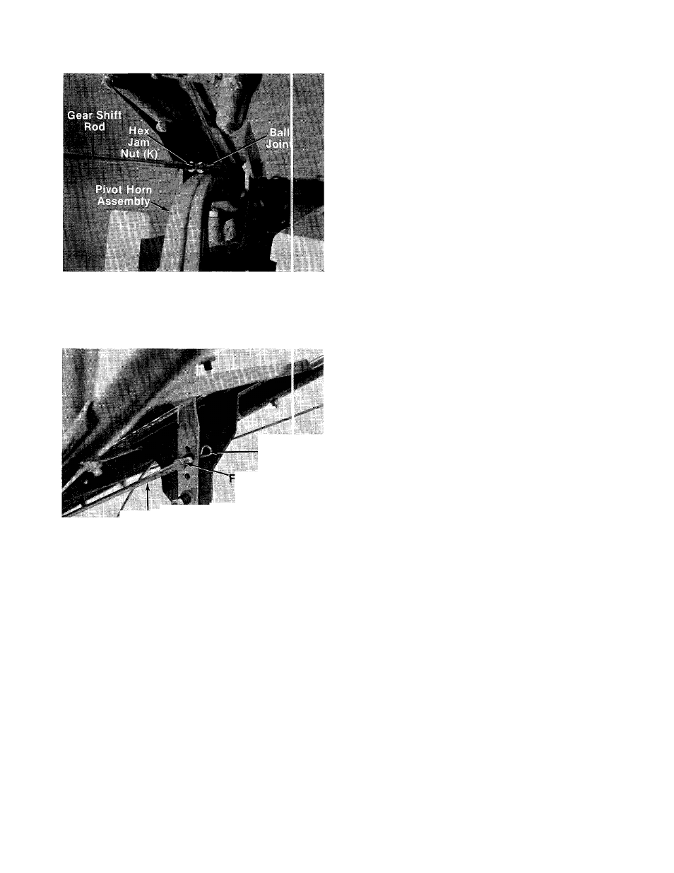
3. Thread hex jam nut (K) on one end of gear shift
rod. Then thread gear shift rod into ball joint
on the top of pivot horn assembly 10 to 12
complete turns, approximately I
/2
inch. See
—figure 12. Lock hex jam nut against ball joint.
FIGURE 12.
Gear Shift ^bd
in Front of
Gear Shift Lever
Hairpin
Cotter (D)
errule (J)
4. Thread ferrule (J) on other end of gear shift
— rod. See figure 13.
5. Secure ferrule in gear shift lever as shown in
figure 13 with hairpin cotter (D).
After all assembly is completed,
the gear shift rod must be ad
justed prior to initial operation.
FIGURE 13.
Gear Shift Rod Adjustment
A
CAUTION
Service engine with oil and gasoline
before making this adjustment.
Refer to the separate engine
manual packed with your tiller.
1. Place the gear shift lever in “NEUTRAL” (N)
position.
2. Place the tine engagement lever in the
disengaged position. See figure 22.
3. Place wheel engagement lever in the
disengaged position. See figure 23.
4. Place the throttle in the “START” position.
5. Move choke lever down (if engine is cold). See
figure 17.
6. Start the engine.
7. Engage the gear shift lever through the five
gears with the engine running and return to
“NEUTRAL” (N).
8. Stop the engine.
9. Remove the hairpin from ferrule and pull out
of gear shift lever.
10. Place gear shift lever in first gear (and pull
lever to rear of slot). Adjust the ferrule to fit
gear shift lever, and replace the hairpin.
11. Repeat steps 6 through 10 to make the final
adjustment.