Air cleaner, Cleaning engine and tine area, Spark plug – MTD 214-412-000 User Manual
Page 15: Fuel shut-off valve and filter, Warning, Note, Belt replacement, Caution
Attention! The text in this document has been recognized automatically. To view the original document, you can use the "Original mode".
Check oil level every eight hours of operation. Be
sure level is maintained full to point of overflow
ing.
AIR CLEANER
Under normal operating conditions, the air
cleaner, located on top of the carburetor, must be
serviced after every ten hours of use. Under ex
tremely dusty operating conditions, the air
cleaner must be serviced after every hour of
operation.
To service the air cleaner, refer to the separate
engine manual packed with your tiller.
A
CAUTION
Never run your engine without air cleaner com
pletely assembled.
CLEANING ENGINE AND TINE AREA
Any fuel or oil spilled on the tiller should be wiped
off promptly. Dirt, leaves and other debris must
not be left to accumulate around the cooling fins
or the engine or on any part of the tiller. Clean the
underside of the tine shield after each use. The
dirt washes off the tines easier if washed off im
mediately instead of after it dries.
SPARK PLUG
The spark plug should be cleaned and the gap
reset every 25 hours of engine operation. Spark
plug replacement is recommended at the start of
each tiller season; check engine manual for cor
rect plug type and gap specification.
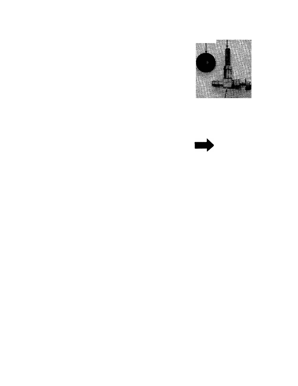
FUEL SHUT-OFF VALVE AND FILTER
The valve and filter is located on the bottom of the
gasoline tank located on top of the tiller.
Turn the valve knob in to shut off the fuel flow.
Turn the valve knob out to operate the tractor. See
figure 29.
The entire valve can be pulled out to clean the
filter. When reassembling, place the rubber grom
met into the gasoline tank first, then push the
valve all the way in.
\ WARNING \
Only use factory approved parts if
repairs are needed on the gasoline
tank, grommet, valve or gasoline
line.
Grommet
Filter
Valve
FIGURE 29.
LIMITED TORQUE CLUTCH
If the limited torque clutch is disassembled for
any reason, reassemble as shown on page 22.
NOTE
Torque setting is 550 to 650 in. lbs.
If you do not have a torque wrench, proceed as
follows:
1. Run the first nut on until it touches the spring
bell washer.
2. Mark nut and plate with a scrib line.
3. Tighten nut 3/4 of a turn clockwise.
4. Then lock in place with the second hex jam
nut.
BELT REPLACEMENT
A
CAUTION
Do not use an off-the-shelf belt.
Your tiller has been engineered with belts made of
special material (Kevlar Tensile) for longer life and
better performance. They should not be replaced
with an off-the-shelf belt.
If belt replacement is required, order belt or belts
by part number from your nearest authorized
dealer.
Part No. 754-0220
Part No. 754-0268
5/8"
X
27" Short Belt 5/8" x 51" Long Belt
Front (Short) Belt Removal
1. Remove belt cover by removing the four self
tapping screws and flat washers. See figure
30.
A
, CAUTION
Muffler may be hot in the area
of belt cover. Only remove the belt
cover when engine is cool.
15