Assembly, Note – MTD 214-412-000 User Manual
Page 4
Attention! The text in this document has been recognized automatically. To view the original document, you can use the "Original mode".
ASSEMBLY
Depth iar
Adjustrr ent
Plate
NOTE
This unit is shipped WITHOUT GAS
OLINE or OIL. After assembly, see
separate engine manual for proper
fuel and engine oil recommenda
tions.
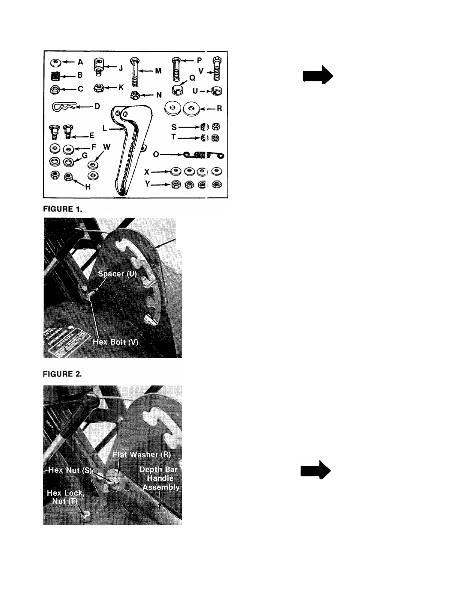
-Contents of Hardware Pack: (See Figure 1)
A (1) Belleville Washer 3/8" I.D.
B (1) Compression Spring
0 (1) Hex Lock Nut 3/8-24 Thread
D (1) Hairpin Cotter
E (2) Shoulder Bolts
F (2) Belleville Washers V
2
" I.D.
G (2) Flat Washers V
2
" I.D.
H (2) Hex Top Lock Nuts 3/8-16 Thread
J (1) Ferrule
K (1) Hex Jam Nut 3/8-24 Thread
L (1) Handle Adjustment Lever
M (1) Hex Bolt
1
/
4-20
X
1.75" Long
N (1) Hex Lock Nut
1
/
4-20
Thread
O (1) Spring
P (1) Hex Bolt 3/8-16
X
1.75" Long
Q (1) Spacer .38" Long
R (2) Flat Washers 3/8" I.D.
S (2) Hex Nuts 3/8-16Thread
T (2) Hex Lock Nuts 3/8-16 Thread
U (1) Spacer .18" Long
V (1) Hex Bolt 3/8-16
X
1.5" Long
W (2) Flat Washers
1
/
4
" I.D.
X (4) Belleville Washers 5/16" I.D.
Y (4) Hex Nuts 5/16-18 Thread
■DEPTH BAR INSTALLATION
1. Grease the depth bar adjustment slots with an
automotive chassis grease.
2. Place hex bolt (V) through the hole in the
depth bar adjustment plate as shown in figure
2. The head of the bolt must be to the right
side of the tiller. Place smaller spacer (U) on
the hex bolt.
¡*■1
FIGURE 3.
NOTE
The right and left side of your tiller
is determined from operator’s posi
tion.
■
3
. Place slot in depth bar handle assembly over
the spacer and hex bolt. Secure with flat
washer (R) and hex nut (S), tightening secure
ly. Place one end of spring (O) onto the bolt.
Thread hex lock nut (T) on the bolt until the
two nuts are approximately 1/8" apart. See
figure 3.