Assembly of engagement rod and handle – MTD 24642S User Manual
Page 7
Attention! The text in this document has been recognized automatically. To view the original document, you can use the "Original mode".
PIVOT
BRACKET
SHOULDER
BOLT (P)
EXTENSION
SPRING (Y)
HEX
NUT(R)
HEX
BOLT (T)
> ^
\
lock
WASHER (Q)
'
^
\l
PIVOT
STAND
HEX ■
NUT (V)
FIGURE 6
HEX
LOCK NUT
(W)
CENTER LINK'
:ON CHAIN
FLAT WASHER
i X )
HEX
BOLT (F)
FIGURE 7
ENGAGEMENT
7.
Thread hex nut (V) onto hex bolt (T). Secure tc
pivot stand with hex lock nut (W) as shown in
figure 6.
8.
Assemble the pivot stand to the pivot brackets
with two shoulder bolts (P), lock washers (Q)
and hex nuts (R).
9.
Attach extension spring (Y) to long hex bolts on
tow hitch and pivot stand. See figure 6.
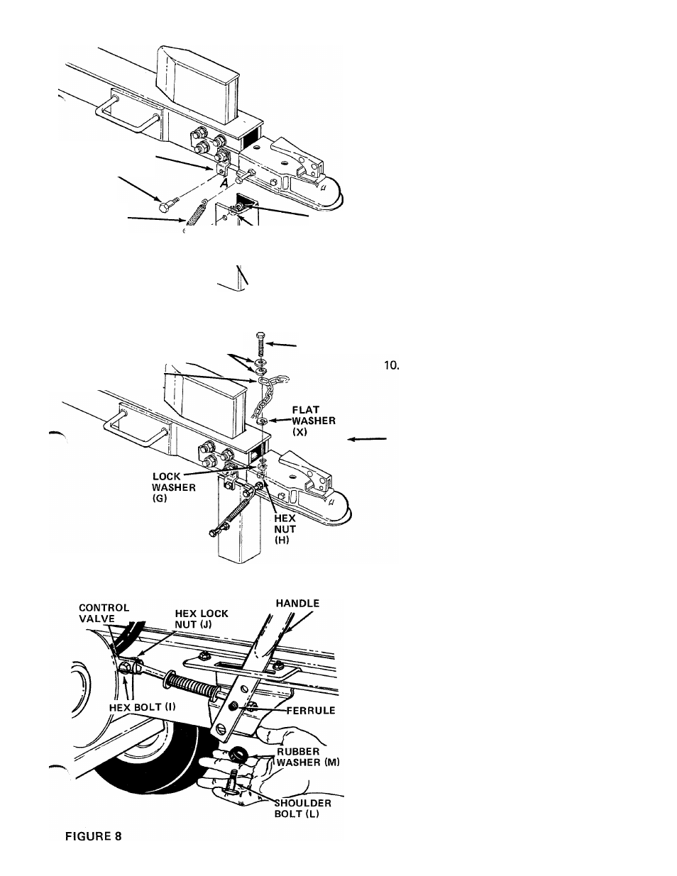
Find the center link of the tow hitch chain.
Place two special flat washers (X) on hex bolt (F),
then the center link on chain and another flat
washer (X). Insert bolt down through the hole in
the tow hitch assembly which is nearest the wedge.
Secure with lock washer (G) and hex nut (H).
See figure 7.
ASSEMBLY OF ENGAGEMENT ROD AND HANDLE
2
.
1.
Attach the engagement rod assembly to the
control valve with hex bolt (I) and hex lock nut
(J) as shown in figure 8.
Place the flattened end of the engagement handle
down through the slotted bracket beside the beam.
Insert the end of the ferrule on the engagement
rod into the second hole from the end of the
engagement handle. See figure 8.
Place shoulder bolt (L) through bottom hole in
engagement handle. Place rubber washer (M) on
shoulder bolt. Secure to bracket with lock washer
(G) and hex nut (N).
3.