Assembly of tow hitch and stand – MTD 24642S User Manual
Page 6
Attention! The text in this document has been recognized automatically. To view the original document, you can use the "Original mode".
HUBCAP
TAPERED
BEARING
(TAPER TO
INSIDE)
SPACER
TAPERED (A)
ROLLER _
BEARING (B)
HUB
CAP (E)
COTTER
HEX CASTLE
NUT (C)
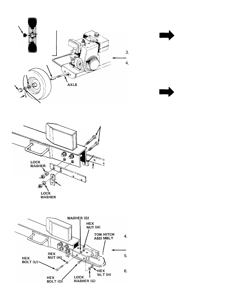
FIGURE 3
3-1/2" LO MG
HEX BOLTS
PIVOT
BRACKET (Z)
HEX^
nut
\
TOW HITCH
BRACKETS
PIVOT
BRACKET (Z)
FIGURE 4
LOCK
FIGURE 5
2.
Pack the tapered roller bearings (B) with auto
motive grease provided.
NOTE
Do not put any grease in the hub caps.
Place one spacer (A) on the axle, then one wheel
and a tapered roller bearing (B). See figure 3.
Thread hex castle nut (C) on axle. Tighten castle
nut until snug, then back off approximately 1/3
turn or until one of the slots on the castle nut
lines up with hole in axle. Secure castle nut to
axle with cotter pin (D). See figure 3.
NOTE
Make certain wheel bearings were
packed with grease.
5. Place hub cap (E) in position on wheel and tap
on with a plastic hammer.
6. Repeat steps 3 through 6 for the second wheel.
ASSEMBLY OF TOW HITCH AND STAND
The wedge is already assembled to the log splitter,
and is held in place with four 3-1/2" long hex bolts,
lock washers and hex nuts. The top two bolts and.,
nuts are tightened securely. The bottom two bolts a'
nuts have been assembled loosely.
1. Remove the two bottom bolts, lock washers and
—■ hex nuts from the beam and wedge. See figure 4.
2.
Place one tow hitch bracket on each side of the
beam, lining up the large holes in the brackets
with the bottom holes in the beam. Secure the
tow hitch brackets with one hex bolt, lock washer
and hex nut just removed.
3.
Place one pivot bracket (Z) on each side of the
two hitch brackets, lining up the holes in the
hitch bracket with the holes toward the end of the
beam. The pivot brackets must be assembled with
the bend to the outside as shown in figure 4.
Secure with the other hex bolt, iock washer and
hex nut removed in step 1.
Place the tow hitch assembly in position on the
tow hitch brackets. Secure the left side of tow
hitch assembly with two hex bolts (0), lock
washers (G) and hex nuts (H). See figure 5.
Secure the right hand side of tow hitch assembly
with hex bolt (0), lock washer (G) and hex nut
(H) in the front hole only.
_
Thread one hex nut (H) onto hex bolt (U). Secu
rear hole in tow hitch assembly with this bolt,
lock washer ( G ) and another hex nut (H).
NOTE: Spring (Y) will be attached to this bolt in step
9.