SINGER 99-13 User Manual
Page 20
Attention! The text in this document has been recognized automatically. To view the original document, you can use the "Original mode".
Rüffler
Lines 1, 2, 3, -1
and
5
slniwii in
Kij{. 35
indieate
wliori! fill! iiiaUrial is to lie, planed for Various
o()erafioiis, as follows:
8
38
14
13
E 5152
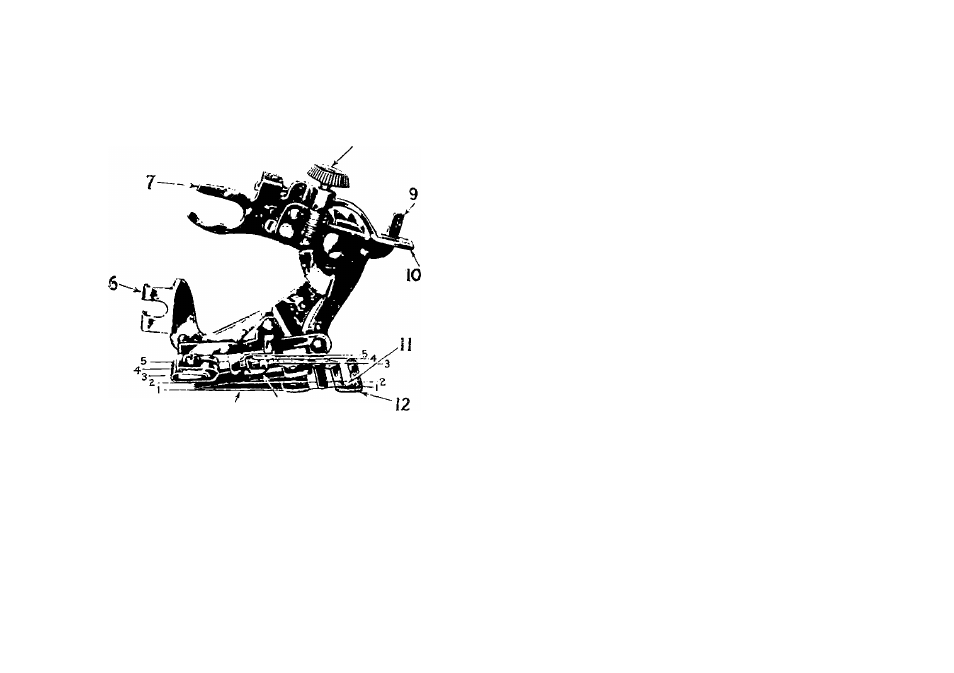
Fiu. 35. Tue UuFt'i.tac .v.\ii u's F.
vkts
Line 1—the correct po.silion for llie inalerial to
which the. riillled material js aiiplied.
Line 2—material to he (iatheroil.
Line 3—ihe facing for the rullle.
Line 4- the strip of piping material.
Line 5—the edge to be piped.
Refer to h'ig. 35 when inserting the material in
the miller.
3'J
The names and u.ses of the principal parts of the
Inltler are as follows:
(H
kis
: N4>
ü
. tN So)
6—
Foot—the part by which the rnHler is atliudied
to the presser liar.
7—
Fork Arm—Ihe section that must he placed
aslrido the needle clamp.
8—
Adjusting Screw the screw that regulates
the fullness of the gather.
9—
Projection—the. part that projects throngli the
.slots in the adjnsling lever.
10—
Adjusting Lever—the
lever
that
Sets
the
miller for plain gathering nr plaiting.
11—
Heading Guide— guide for the heading of the
rnllle.
12—
Separator Plate—tlie gniile on the mulerside
of
the
miller,
containing
several
.slots
inlo
which the edge of the inalerial is slipped to
keep the heading of the rullle even.
13
Ruffling
Blade—the
upper
hlne
steel
bhule
with teeth at the end to posh the inalerial in
plails up to the needle.
14—Separator
Blade
—the
lower
blue
steel
lilude
without
teeth,
which
inevenls
the
teeth
of
the
milling
blade
eoming
into
contact
with
the teeth of the feed ihig.
To Attach the Ruffler to the Machine
Raise the needle liar to its highest point and re-
lunve the pre.s.ser foot. Attach the miller foot to the
lire.sser bar by means of the thumb screw, at the
same
time
placing
the
fork-arm
astride
the
needle
clamp as shown in Fig. 3li.